Archive for the ‘ Coding ’ Category

Updated Weather Station

Working on updating my weather station currently. It’s been out of commission for a year or so. The rubbermaid box I had it in didn’t last in the elements so I’m having to rethink my mounting process. I’m also looking into getting a larger battery because the 6000 maH one I’m using doesn’t last that long.

I’m also going to be improving it. I’ve put together a circuit to measure how much battery I have left so I can have it turn itself off when the battery is too low. Also have a few more calculations that I can add in to my reporting like heat index which will be useful for the summer.

I’ve also reordered my posts so you will see the updated weather station posts below this one to try to group them in an order of build process

Wind Direction Reading

As I stated in the previous post, the readings of this sensor take a lot of work to setup. You have to get a reading at each direction and then split the difference between them to get a high and low. Somewhere I have an excel file that I use to do all the calculations and print out the code. I’ll load it here if/when I find it.

To use this, you will need to place an include in your python program:

from wind_dir import wind_dir

Then when you want to get the value, you call the function with your ADC reading:

wind_direction = wind_dir(wind_dir_read)

The annoying part of this is setting up this file. All it does is take your reading and see where it falls within the table of max & min values established through testing:


#!/usr/bin/env python

wind_dir_high_NNE=962
wind_dir_high_NE=937
wind_dir_high_ENE=885
wind_dir_high_E=839
wind_dir_high_ESE=798
wind_dir_high_SE=760
wind_dir_high_SSE=726
wind_dir_high_S=695
wind_dir_high_SSW=667
wind_dir_high_SW=641
wind_dir_high_WSW=616
wind_dir_high_W=593
wind_dir_high_WNW=571
wind_dir_high_NW=550
wind_dir_high_NNW=535
wind_dir_low_NNE=935
wind_dir_low_NE=884
wind_dir_low_ENE=838
wind_dir_low_E=797
wind_dir_low_ESE=759
wind_dir_low_SE=725
wind_dir_low_SSE=694
wind_dir_low_S=666
wind_dir_low_SSW=640
wind_dir_low_SW=615
wind_dir_low_WSW=592
wind_dir_low_W=570
wind_dir_low_WNW=549
wind_dir_low_NW=534
wind_dir_low_NNW=527

def wind_dir(amt):
if amt <= wind_dir_high_NNE and amt >= wind_dir_low_NNE:
wind_direction = 'NNE'
elif amt <= wind_dir_high_NE and amt >= wind_dir_low_NE:
wind_direction = 'NE'
elif amt <= wind_dir_high_ENE and amt >= wind_dir_low_ENE:
wind_direction = 'ENE'
elif amt <= wind_dir_high_E and amt >= wind_dir_low_E:
wind_direction = 'E'
elif amt <= wind_dir_high_ESE and amt >= wind_dir_low_ESE:
wind_direction = 'ESE'
elif amt <= wind_dir_high_SE and amt >= wind_dir_low_SE:
wind_direction = 'SE'
elif amt <= wind_dir_high_SSE and amt >= wind_dir_low_SSE:
wind_direction = 'SSE'
elif amt <= wind_dir_high_S and amt >= wind_dir_low_S:
wind_direction = 'S'
elif amt <= wind_dir_high_SSW and amt >= wind_dir_low_SSW:
wind_direction = 'SSW'
elif amt <= wind_dir_high_SW and amt >= wind_dir_low_SW:
wind_direction = 'SW'
elif amt <= wind_dir_high_WSW and amt >= wind_dir_low_WSW:
wind_direction = 'WSW'
elif amt <= wind_dir_high_W and amt >= wind_dir_low_W:
wind_direction = 'W'
elif amt <= wind_dir_high_WNW and amt >= wind_dir_low_WNW:
wind_direction = 'WNW'
elif amt <= wind_dir_high_NW and amt >= wind_dir_low_NW:
wind_direction = 'NW'
elif amt <= wind_dir_high_NNW and amt >= wind_dir_low_NNW:
wind_direction = 'NNW'
else:
wind_direction = 'N'

return wind_direction

As you can see from the above, I get all the way down to the minor directions such as “NNE” & “ESE”, etc. You can change it to suit your needs.

Rain Gauge

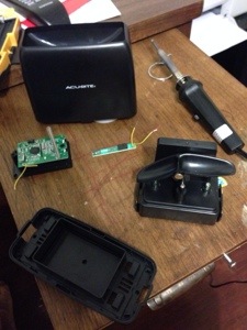
The rain gauge to me was one of the easiest to do, mostly because I kind of cheated a bit. Since I didn’t think I could create a sensor for cheaper than I could buy one, I spent $20 and bought the Acu-Rite gauge at Wal-Mart and modified it to my needs.

20131130-084727.jpg

To start off, you’ll need to take apart the “gauge” piece and set the wireless display aside. This is fairly easy, as the main cover and tipping part comes off fairly easy. Next, you’ll need to remove the screws under the battery compartment to remove the circuit board. There are two wires coming out of the circuit board that go to the reed switch within the gauge that need to be clipped.

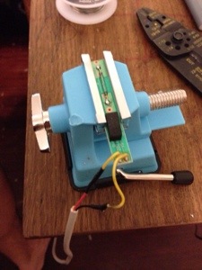
20131130-084735.jpg

The reed switch is set within the tipping part, so carefully pull it out and strip the wires. You’ll need to attach wires to each of these. I use some telephone cable/cat3. I usually start with attaching about 10 feet of wire just in case. When attaching, make sure you solder the wires and use shrink tube to protect the connection.

20131130-084745.jpg

Next, carefully slide the reed switch back into the tipping piece. Real quick explanation of how this works….A reed switch “closes” when a magnetic field is near. So we run current through the reed switch and place a magnet in the tipping mechanism to pass over the reed switch when it tips. When rain fills up a side of the gauge it tips over and the magnet causes the reed switch to complete the circuit for a brief period, which we can count….

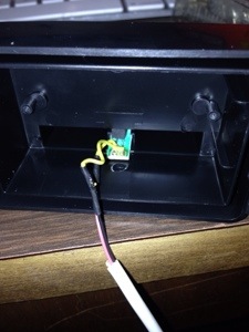
20131130-084757.jpg

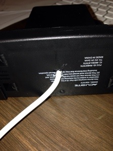
We then need to drill a hole in the battery compartment and in the bottom piece to allow the wire to go through. Make sure to put a little hot glue in the hole in the bottom to protect against the elements a bit.

For testing, plug the two wires into a breadboard, one needs to run to power and the other to one of the pins on the Raspberry Pi (I believe I use number 17). In order to count how many times the gauge tips, we have to use GPIO interrupts. Before I forget, each tip is .02 inches of rain….

To keep count, I use a script that runs when the Pi starts up and monitors that pin. When the gauge tips and it detects a voltage “spike” it opens a file, takes the number, adds 1 to it and then rewrites the file with that number. (When I run the script that gets the current weather, I access this file and multiply by .02) At midnight every night, I also run a script that resets the number in the file to 0.

Here is the file I use to monitor the pin…

#!/usr/bin/env python2.7

import time
import os
import RPi.GPIO as GPIO
GPIO.setmode(GPIO.BCM)

First bit is to set up the normal stuff…I have to give some credit to Alex Eames @ http://RasPi.tv/ for the pieces of interrupt code. http://raspi.tv/2013/how-to-use-interrupts-with-python-on-the-raspberry-pi-and-rpi-gpio


# GPIO 17 set up as input. It is pulled up to stop false signals
GPIO.setup(17, GPIO.IN, pull_up_down=GPIO.PUD_DOWN)

Next we need to set up the pin for interrupts. We’re setting up pin 17 as an input and using an internal resistor to pull it down to 0 when there is no current.


def my_callback(channel):
tfile = open("/home/pi/rain_count.txt")
text = tfile.readline()
tfile.close()

rain_count = int(text)
rain_count += 1
tfile = open("/home/pi/rain_count.txt", "w")

tfile.write(str(rain_count))
tfile.close()

Now we create the function that gets called when a “spike” is detected. This function opens the file called “rain_count.txt” and reads the number, adds one and then writes the new number to the file. When doing this, don’t forget to create the rain_count.txt file prior to running this and place a 0 in it.


GPIO.add_event_detect(17, GPIO.RISING, callback=my_callback, bouncetime=300)

Now we add the interrupt event that monitors pin 17 and says that we want to monitor it for a rising event (I call a spike). When it is detected it calls the function “my_callback” and then waits 300 milliseconds before it will try to detect another one. (The bounce time is necessary to keep from getting false positives.)


while True:
time.sleep(60)

The last bit is just an infinite loop to keep the script running. To run this at startup of the Pi, you’ll need to add a line to the crontab file:

@reboot python /home/pi/rain-gauge.py &

The clearing file is fairly easy too….
#!/usr/bin/env python2.7
import time
import os

tfile = open("/home/pi/rain_count.txt", "w")
rain_count = 0
tfile.write(str(rain_count))
tfile.close()

And add this to your crontab file to run at midnight…
* 0 * * * /home/pi/rain-clear.py

The last bit is grabbing the count when you run the the weather script…
#get rain amount
rain_file = open("/home/pi/rain_count.txt")
rain_gauge = rain_file.readline()
rain_file.close()

rain_count = int(rain_gauge)

rain_count =float(rain_count) * .02

rain_count = round(rain_count, 1)

The only thing I’ll mention here since it’s pretty straight forward is that you’ll notice I do a round at the end. I’ve experienced some false positives during the day when it’s sunny (usually 1 or 2 a day), so I just get rid of them by rounding to the nearest 10th.

Mast – Micro controller code

Below is the arduino code I use for the Pro Mini.  I’m going to post it in block quotes as well as a link to a txt file with the code.  I feel that it’s commented well so I’m not going to go into details here.  It uses the standard Wire, OneWire & AVR/Interrupt libraries as well as some found code for the DS18B20 reading.  I’m planning on loading all my code to Github in the future so it’s all in one place.  I just have to figure out how to do that appropriately.  (Since some of the libraries I use for sensors come from other sources, ie: Adafruit)

#include <Wire.h>
#include <avr/interrupt.h>
#include <OneWire.h>

// defining which I2C addres to use
#define SLAVE_ADDRESS 0x05
// setting he number used to request data from pro mini to send back to the pi
int number = 0;

//setting up pins for sensors
const byte rainGauge = 2;
const byte windSpeed = 3;

// setting up variables for sensors
volatile int rainCount = 0;
volatile int windCount = 0;
volatile int windCountSend = 0;
volatile int windCountSendMax = 0;
long rainDebouncingTime = 300; //Debouncing Time in Milliseconds
volatile unsigned long rainLastMicros;
long windDebouncingTime = 100; //Debouncing Time in Milliseconds
volatile unsigned long windLastMicros;
volatile int windDir = 0;

int temp = 0;
// pin for DS18B20
OneWire ds(10); // on pin 10

void setup() {

// initialize i2c as slave
Wire.begin(SLAVE_ADDRESS);

// define callbacks for i2c communication
Wire.onReceive(receiveData);
Wire.onRequest(sendData);

// setup pins for sensors and attach interrupts
pinMode(rainGauge, INPUT);
digitalWrite (rainGauge, HIGH); // internal pull-up resistor
attachInterrupt (0, debounceRain, FALLING); // attach interrupt handler
pinMode(windSpeed, INPUT);
digitalWrite (windSpeed, HIGH); // internal pull-up resistor
attachInterrupt (1, debounceWind, FALLING); // attach interrupt handler
Serial.begin(9600);

}

void loop() {

//***********************************
// Read DS18B20
int HighByte, LowByte, TReading, SignBit, Tc_100, Whole, Fract;

byte i;
byte present = 0;
byte data[12];
byte addr[8];

if ( !ds.search(addr)) {
ds.reset_search();
return;
}

ds.reset();
ds.select(addr);
ds.write(0x44,1); // start conversion, with parasite power on at the end

delay(1000); // maybe 750ms is enough, maybe not
// we might do a ds.depower() here, but the reset will take care of it.

present = ds.reset();
ds.select(addr);
ds.write(0xBE); // Read Scratchpad

for ( i = 0; i < 9; i++) { // we need 9 bytes
data[i] = ds.read();

}

LowByte = data[0];
HighByte = data[1];
TReading = (HighByte << 8) + LowByte;
SignBit = TReading & 0x8000; // test most sig bit
if (SignBit) // negative
{
TReading = (TReading ^ 0xffff) + 1; // 2’s comp
}
Tc_100 = (6 * TReading) + TReading / 4; // multiply by (100 * 0.0625) or 6.25

temp = Tc_100;

//************************************

// get wind speed
windCount = 0;
delay(10000);
windCountSend = windCount;
if (windCountSend > windCountSendMax){
windCountSendMax = windCountSend;
}

}

// callback for received data
void receiveData(int byteCount){

while(Wire.available()) {
number = Wire.read();
// setup to reset rain count. R-Pi sends this at midnight to reset
if (number == 8){
rainCount = 0;
}

}
}

// callback for sending data
void sendData(){
byte sendData[2];
int sendVal = 0;
if (number == 1){
sendVal = rainCount;

}
// wind speed
else if (number == 2){
sendVal = windCountSend;

}
// wind direction
else if (number == 3){
sendVal = analogRead(1);
}
// wind gust speed
else if (number == 4){
sendVal = windCountSendMax;
windCountSendMax = 0;

}
// temperature
else if (number == 5){
sendVal = temp;
}
// humidity
else if (number == 6){
sendVal = analogRead(2);
}

else {
sendVal = number;
}
// sending requested data to the Pi
sendData[0] = (byte) sendVal & 0xFF;
// Serial.println(sendData0, HEX);
sendData[1] = (byte) (sendVal >> 8) & 0xFF;
// Serial.println(sendData1, HEX);
Wire.write(sendData, 2);
//Wire.write(sendData0);
//Wire.write(sendData1);
}

// debouncing of interrupt sensors so only count once per action
void debounceRain() {
if((long)(micros() – rainLastMicros) >= rainDebouncingTime * 1000) {
rainFunc();
rainLastMicros = micros();
}
}

void debounceWind() {
if((long)(micros() – windLastMicros) >= windDebouncingTime * 1000) {
windFunc();
windLastMicros = micros();
}
}

// incrementing the variables used for counting sensors
void rainFunc() {
rainCount++;
Serial.print(rainCount);
}

void windFunc() {
windCount++;
Serial.println(windCount);
}

Link to file

Anemometer Reading

It was too late last night when I finished the post about building the anemometer that I didn’t want to get into the code to read the wind speed. As I said before, basically what I do is I count the number of “triggers” within a 10 second period and then feed that into the formula that came from testing it with our car.

Here is the code I use for Raspberry Pi…I run this every 5 minutes (with the rest of my measurements) to get the wind speed at that time.

# calculate windspeed
# set up the GPIO to be an input and activate the internal resistor to pull down the pin to low
GPIO.setup(22, GPIO.IN, pull_up_down=GPIO.PUD_DOWN)

# This is the interrupt function. It opens a file, pulls the number from the file and adds one to it, then rewrites it to the file.
def wind_callback(channel):
windfile = open("/home/pi/wind_count.txt")
windtext = windfile.readline()
windfile.close()

wind_count = int(windtext)
wind_count += 1
windfile = open("/home/pi/wind_count.txt", "w")

windfile.write(str(wind_count))
windfile.close()

# Here is the interrupt setup. We are setting it up on pin 22, looking for it to rise, calling the function "wind_callback" when it is triggered and
# debouncing it by 100ms
GPIO.add_event_detect(22, GPIO.RISING, callback=wind_callback, bouncetime=100)
# Before we start the count, we open the file and set the number to 0
windfile_clear = open("/home/pi/wind_count.txt", "w")
wind_count_clear = 0
windfile_clear.write(str(wind_count_clear))
windfile_clear.close()

# now we sleep for 10 seconds to get the readings
time.sleep(10)

# After sleeping, we open the file and read the number
wind_file = open("/home/pi/wind_count.txt")
wind_count = wind_file.readline()
wind_file.close()

# in order to use it in some math, we need to convert it to an int
wind_count_comp = int(wind_count)

# here is the formula created from testing. Basically it is .0023427x^2 + .46244x
windspeed_a = wind_count_comp * wind_count_comp * .0023427
windspeed_b = wind_count_comp * .46244
windspeed = windspeed_a + windspeed_b

# round it off to 1 decimal.
windspeed = round(windspeed, 1)

I am actually in the middle of a redesign on my weather station due to the Raspberry Pi not being the best at interrupts for the rain gauge. For the one at my father-in-laws farm, I will be using an Adafruit trinket to capture all the data from the anemometer, rain gauge, and wind direction sensor before relaying it to the Pi. This type of sensing is better for a micro controller than it is for a Linux computer such as the Pi. For my home weather station, I’ll be using a Arduino Pro Mini as I have a lot more sensors on my mast. The Trinket code is a little more difficult due to the ATTiny85 that runs it. I’ll post info on how to connect it to a Raspberry Pi later.

Here is the code for the same principal as above on a trinket. The big difference here is that this runs constantly. Every 10 seconds I have a wind speed reading, although I only pull it every 5 minutes.


#include avr/interrupt.h

// setup cbi & sbi for interrupts
#ifndef cbi
#define cbi(sfr, bit) (_SFR_BYTE(sfr) &= ~_BV(bit))
#endif
#ifndef sbi
#define sbi(sfr, bit) (_SFR_BYTE(sfr) |= _BV(bit))
#endif

// Set up variables used
volatile int windSpeed = 0; // keep track of interrupts from anemometer
volatile int windSpeedSend = 0; // used to send 10 second interrupt value to pi
long debouncing_time_wind = 100; //Debouncing Time in Milliseconds for anemometer
volatile unsigned long last_micros_wind; // micros since last anemometer interrupt
volatile int val2 = 0; // pin 4 value at interrupt

void setup()
{
// Setup Pins for interrupts
pinMode(4,INPUT);

sbi(GIMSK,PCIE); // Turn on Pin Change interrupt
sbi(PCMSK,PCINT4); // Which pins are affected by the interrupt. Turn on Pin 2

}

void loop()
{

// anemometer counts interrupts for 10 second interval. This is sent to master for calculation
windSpeed = 0;
tws_delay(10000);
windSpeedSend = windSpeed;

}

// debounce anemometer. make sure new reading is greater than old reading + debounce wind micros
void debounceWindSpeed() {
if((long)(micros() - last_micros_wind) >= debouncing_time_wind * 1000) {
windSpeedFunc();
last_micros_wind = micros();
}
}

// function to increment anemometer count
void windSpeedFunc() {
windSpeed = windSpeed + 1;
}

// interrupt service routine. What to do when an interrupt occurs as all pin change interrupts
// on ATTiny85 trigger PCINT0 vector.
ISR(PCINT0_vect) {
// get value of pin 4 @ interrupt
val2 = digitalRead(4);

// if pin 4 is HIGH (caused the interrupt), proceed with wind speed (anemomether) increment function
if (val2 == HIGH) {
debounceWindSpeed();
}

}

I finally completed migrating the weather sensors for the weather station that is at my father-in-law’s farm. I had issues with the rain gauge not working too well with the pi directly, so I decided to use an Adafruit Trinket to capture the values of the sensors and send them to the pi for tracking. The communication between the two is accomplished using I2C.

image

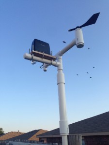
Here’s the completed mast with sensors attached. (This is actually a pic of it at my house for testing) What you’ll need for this is 1 of each of an anemometer, wind vane & rain gauge. It works with the sensors I built, but I’m sure you could incorporate it to use any sensors you have as well.

I’ve used PVC to build all my sensors as it’s easy to connect together. In my anemometer & wind vane posts I have used certain PVC pieces to allow for connection to my mast. For the rain gauge, it’s a little different. I used a piece of cedar fence board to secure the sensor, then some u-bolts to attach the board to a 1 inch pvc pipe, plugged one end and drilled a hole for the wire to run through.

For the rest of the top part of the mast I use a 1″ T-connector at the top with about 8 or so inches of 1″ pipe to connect the anemometer & wind vane. I run the wires down through the pipes. I then use a small piece of 1 inch pipe (about 3 or so inches) to connect another T-connector for the anemometer. I then use another portion of 3 or so inches of 1″ pvc pipe to connect to the lower portion. (Sorry, but I don’t have any pics of this…)

The lower mast is where the trinket comes in…I connect all the sensor wires to a single cat 5 cable to connect to trinket and then another wire for the I2C communication. The idea is to house the trinket in some 3/4″ pipe that is waterproofed and have it sit inside some 1 1/2″ pipe. (You can see this bulge in the pic above) I use some connectors to move from 1″ to 1 1/2″ pipe. Then a portion of 1 1/2″ pipe (I think it’s 12 inches long) and then connect it back to another 1″ piece of pipe to mount it.

Before wiring up your trinket, make sure you upload the code to it. Here is what I use which tracks the sensors and sends the data via I2C:

#include avr/interrupt.h
#include TinyWireS.h

// setup cbi & sbi for interrupts
#ifndef cbi
#define cbi(sfr, bit) (_SFR_BYTE(sfr) &= ~_BV(bit))
#endif
#ifndef sbi
#define sbi(sfr, bit) (_SFR_BYTE(sfr) |= _BV(bit))
#endif

//Define address of device
#define I2C_SLAVE_ADDRESS 0x04

// Set up registers to hold data to send
volatile uint8_t reg[] =
{

0xDE,
0xAD,
0xBE,
0xEF,
0xEE,
0xED
};

// Set up variables used

volatile byte reg_position; // keep track of reg position sent from master
volatile int rainGauge = 0; // keep track of interrupts from rain gauge
volatile int windSpeed = 0; // keep track of interrupts from anemometer
volatile int windDirection = 0; // keep track of value of wind direction sensor
volatile int windSpeedSend = 0; // used to send 10 second interrupt value to pi
long debouncing_time_rain = 300; //Debouncing Time in Milliseconds for rain gauge
volatile unsigned long last_micros_rain; // micros since last rain gauge interrput
long debouncing_time_wind = 100; //Debouncing Time in Milliseconds for anemometer
volatile unsigned long last_micros_wind; // micros since last anemometer interrupt
volatile int val1 = 0; // pin 1 value at interrupt
volatile int val2 = 0; // pin 4 value at interrupt

// Function to send data when it is requested. Sends 2 register positions
// for each request
void onRequest()
{

// Load all values into registers. (even though only 2 will go to master)
reg[0] = lowByte(windDirection);
reg[1] = highByte(windDirection);
reg[2] = lowByte(windSpeedSend);
reg[3] = highByte(windSpeedSend);
reg[4] = lowByte(rainGauge);
reg[5] = highByte(rainGauge);

// send 2 reg positions to master
TinyWireS.send(reg[reg_position]);
reg_position++;

}
// Function to set which register positions you wish to receive
void receiveEvent(uint8_t howMany)
{
reg_position = TinyWireS.receive();

// if requested position is 7, reset rain gauge variable. Will be sent at midnight each day
if(reg_position == 7) {
rainGauge = 0;
}

}

// Setup for connection
void setup()
{
TinyWireS.begin(I2C_SLAVE_ADDRESS);
TinyWireS.onReceive(receiveEvent);
TinyWireS.onRequest(onRequest);
pinMode(1,INPUT);
pinMode(4,INPUT);

sbi(GIMSK,PCIE); // Turn on Pin Change interrupt
sbi(PCMSK,PCINT1); // Which pins are affected by the interrupt. Turn on Pin 1
sbi(PCMSK,PCINT4); // Which pins are affected by the interrupt. Turn on Pin 2
}

void loop()
{

// anemometer counts interrupts for 10 second interval. This is sent to master for calculation
windSpeed = 0;
tws_delay(10000);
windSpeedSend = windSpeed;

// read pin 3 analog value of wind direction sensor
windDirection = analogRead(3);

// Check for connection to be stopped.
TinyWireS_stop_check();
}

// debounce rain gauge. make sure new reading is greater than old reading + debounce rain micros
void debounceRainGauge() {
if((long)(micros() – last_micros_rain) >= debouncing_time_rain * 1000) {
rainGaugeFunc();
last_micros_rain = micros();
}
}

// debounce anemometer. make sure new reading is greater than old reading + debounce wind micros
void debounceWindSpeed() {
if((long)(micros() – last_micros_wind) >= debouncing_time_wind * 1000) {
windSpeedFunc();
last_micros_wind = micros();
}
}

// function to increment rain gauge count
void rainGaugeFunc() {
rainGauge = rainGauge + 1;
} // end of rainGauge

// function to increment anemometer count
void windSpeedFunc() {
windSpeed = windSpeed + 1;
} // end of rainGauge

// interrupt service routine. What to do when an interrupt occurs as all pin change interrupts
// on ATTiny85 trigger PCINT0 vector.
ISR(PCINT0_vect) {
// get value of pin 1 @ interrupt
val1 = digitalRead(1);
// get value of pin 4 @ interrupt
val2 = digitalRead(4);

// if pin 1 is HIGH (caused the interrupt), proceed with rain gauge increment functions
if (val1 == HIGH) {
debounceRainGauge();
}

// if pin 4 is HIGH (caused the interrupt), proceed with wind speed (anemomether) increment function
if (val2 == HIGH) {
debounceWindSpeed();
}

}

So, now to the wiring:
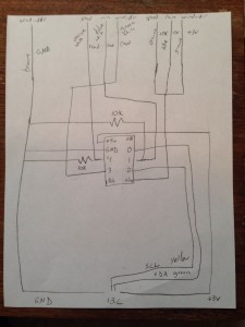
image

Here is the wiring diagram I drew out that shows how everything is connected. When connecting, make sure you use solder and shrink tube to protect the joints.

image

After all the wires are connected, drill a hole in a 3/4″ pvc plug and push the wire through that hole prior to connecting to the trinket. You may want to run it through a piece of 3/4″ pipe as well (about 8 or so inches).

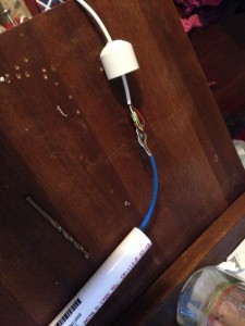
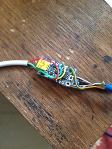
All 3 sensors will need 1 wire connected to the +3v on the sensor. I managed to get all 3 of the cat 5 wires into the hole on the trinket. The read wires will need to go different pins. For the anemometer and rain gauge, you will need to connect a 10k resistor to ground to pull the pin to ground. The rain gauge read wire should go to pin 1 and the read side of the anemometer should go to pin 4. The read wire for the wind vane should go to pin 3. Connecting all the ground wires was fun. What I did was run 1 wire out of the trinket and connected all the ground wires to it and put shrink tube over all of them. (You can see it in the pics below.)

image

image

I didn’t take a lot of single step pics on this and I apologize. You can see the connections for the I2C wire as well in these pics. The last part is connecting the wires for the I2C communications. You’ll want to put the wire through hole in another 3/4″ pvc plug before you connect them to the trinket to allow for waterproofing. Connect the +v to the battery pin (I use 5 volts out of my raspberry pi to power, but you can power it any way you want. I used a 3 volt trinket for this setup). Ground to your ground wire, SDA to pin 0 and SCL to pin 2. Once this is done, slide it all into the 3/4″ pvc and plug the other side. It should look like this:

image

Place some hot glue on each plug where the wires go in to keep the water out, then shove this into the 1 1/2″ pvc pipe and then connect the rest of your mast.

This is really set up to communicate with a pi, but I’m pretty sure it would work with an Arduino as well. In the code you basically send the trinket a number and it will give you the response. Sending 0 will give you the wind direction reading, 2 will give you the wind speed reading and 4 will give you the rain gauge reading. Sending it 7 will cause the rain gauge count to reset. Here’s a quick bit of code you can use for the pi:


#!/usr/bin/python
# Import needed libraries
import smbus
import time

# Set I2C address of device you wish to access
DEV_ADDR = 0x04

bus = smbus.SMBus(1)

# Request values from device. Number is start register position.
while True:
print 'Testing for connection...'
while True:
try:
wind_dir_read = bus1.read_word_data(DEV_ADDR, 0)
wind_count = bus1.read_word_data(DEV_ADDR, 2)
rain_count = bus1.read_word_data(DEV_ADDR, 4)
break
except IOError:
print 'No connection...'
time.sleep(5)
#break
if wind_dir_read < 1030: break else: print 'Value too high.' time.sleep(5) # Use this to reset a variable: #d_val = bus.read_word_data(DEV_ADDR, 7)

It doesn't seem that wordpress knows how to deal with indents in it's code sections, so make sure you indent it properly. Sometimes the trinket can give you some funny business which I've handled via the error trapping above. If you keep this bit of code you shouldn't run into any problems.

When I finished building my weather station it was on a large full size breadboard. I didn’t like that it there was so much space on there that was just wasted and I had a half size sitting around that I thought would work well. Unfortunately, the ADC wouldn’t let everything else fit properly. I did some research and found that Microchip also produced a 2 channel ADC called the MCP3002. Since I was using only 2 channels on the MCP3008, I thought this would work nicely and I counted all the slots on the half size breadboard and it would fit perfectly! So I ordered a couple from Newark…

When they came in I had to test to make sure it was going to work, so I placed in the half size breadboard, wired up a TMP36 analog temp sensor, and connected the breadboard to my spare Pi. Well, come to find out, the driver I had didn’t work. Neither did the other one I found online nor the others I found. I was a bit depressed because I really wanted it to work.

My last hope laid on the Adafruit forums. (Love Adafruit by the way!) I was a bit worried as they don’t sell the MCP3002 and they have messages on there about only supporting their products. So, reluctantly I posted a question on the forum asking if the driver they provide for the MCP3008 would work for the MCP3002. At first their people informed me that it would work, but I told them I had tested it and it didn’t. In one of my responses I made sure that I mentioned that I had wired it as per the datasheet and added a link.

Come to find out, the reason their driver wouldn’t work is because the 3002 only wanted 4 bits sent to it for the request and the 3008 wanted 5. So, Rick (who I think works for Adafruit) helped with adapting that part of the driver. When I added his piece to the 3008 driver, it still didn’t work. I then took another look at the datasheet and found another difference in the 3008 vs the 3002. The 3002 only provided a 11 bit response vs the 12 that the 3008 provided. I then updated the code to account for that and voila! it worked like a charm.

After I got it working, I posted about having to make the other change. Rick then asked me to post the full driver so that it could be added to their python library. So yeah, that’s the story of writing my first driver…

Here it is by the way if you need it:

def readadc(adcnum, clockpin, mosipin, misopin, cspin):
if ((adcnum > 1) or (adcnum < 0)): return -1 GPIO.output(cspin, True) GPIO.output(clockpin, False) # start clock low GPIO.output(cspin, False) # bring CS low commandout = adcnum << 1; commandout |= 0x0D # start bit + single-ended bit + MSBF bit commandout <<= 4 # we only need to send 4 bits here for i in range(4): if (commandout & 0x80): GPIO.output(mosipin, True) else: GPIO.output(mosipin, False) commandout <<= 1 GPIO.output(clockpin, True) GPIO.output(clockpin, False) adcout = 0 # read in one null bit and 10 ADC bits for i in range(11): GPIO.output(clockpin, True) GPIO.output(clockpin, False) adcout <<= 1 if (GPIO.input(misopin)): adcout |= 0x1 GPIO.output(cspin, True) adcout /= 2 # first bit is 'null' so drop it return adcout # change these as desired - they're the pins connected from the # SPI port on the ADC to the Cobbler. There are 2 Chip Select pins. # one for each ADC SPICLK = 18 SPIMISO = 23 SPIMOSI = 24 SPICS = 25 # set up the SPI interface pins GPIO.setup(SPIMOSI, GPIO.OUT) GPIO.setup(SPIMISO, GPIO.IN) GPIO.setup(SPICLK, GPIO.OUT) GPIO.setup(SPICS, GPIO.OUT) Read the rest of this entry

Python Code

So, I finally got around to cleaning up the code a bit and commenting it in order to share it. First off, this is not in any way professional or “clean”. It is just me throwing some stuff down to get it to work. I am not really an OO guy; I think procedurally and so that’s how I code. I have borrowed pieces from others, specifically from Adafruit (the ADC reading code) and I do realize I could be using a lot of loops to run through things, but hey, I’m not worried about size, speed, or cleanliness; just that it works. 🙂 If you are going to use this, be aware of 3 things:
1. You’ll need to sign up for your own API from Weather Underground.
2. You’ll need make sure you’ve installed all the necessary libraries on your Pi. (Read Adafruit’s reading analog data tutorial for this piece. I’ll try to put something together in order to show all of the steps necessary to get this to work.)
3. You’ll need to change your MySQL connection variables

So without further adieu:

#!/usr/bin/env python
import time
import os
import RPi.GPIO as GPIO
import MySQLdb
import urllib2

#set up some GPIO settings
GPIO.setmode(GPIO.BCM)
GPIO.setwarnings(False)

# set up pin that provides power to moisture probes
GPIO.setup(17, GPIO.OUT)
GPIO.output(17, True)

#read inside temperature sensor. temperature = temp in degrees C
tfile = open("/sys/bus/w1/devices/28-000004d608e1/w1_slave")
text = tfile.read()
tfile.close()
temperaturedata = text.split("\n")[1].split(" ")[9]
temperature = float(temperaturedata[2:])
temperature = temperature / 1000

#go get outside humidity from weather underground using api
#reading json file to line that contains humidity and pulling
#out the numbers in the text
req = urllib2.Request('http://api.wunderground.com/api/****************/conditions/q/TX/Forney.json')
response = urllib2.urlopen(req)

read_until = 52
humid_line = 54

correctline = []
correct_humid_line = []
lines = []

for line_number, line in enumerate(response.readlines()):
if line_number == read_until:
correctline.append(line)
elif line_number == humid_line:
correct_humid_line.append(line)
else:
lines.append(line)

pull_humid = ','.join(correct_humid_line)

out_humid = pull_humid[-6:-4]
out_humid = round(float(out_humid),1)

# convert celsius to fahrenheit for inside temp
temp_F = ( temperature * 9.0 / 5.0 ) + 32

# show only one decimal place for temperature
temp_F = "%.1f" % temp_F
temp_C = temperature

# read SPI data from MCP3008 chip, 8 possible adc's (0 thru 7)
def readadc(adcnum, clockpin, mosipin, misopin, cspin):
if ((adcnum > 7) or (adcnum < 0)): return -1 GPIO.output(cspin, True) GPIO.output(clockpin, False) # start clock low GPIO.output(cspin, False) # bring CS low commandout = adcnum commandout |= 0x18 # start bit + single-ended bit commandout <<= 3 # we only need to send 5 bits here for i in range(5): if (commandout & 0x80): GPIO.output(mosipin, True) else: GPIO.output(mosipin, False) commandout <<= 1 GPIO.output(clockpin, True) GPIO.output(clockpin, False) adcout = 0 # read in one empty bit, one null bit and 10 ADC bits for i in range(12): GPIO.output(clockpin, True) GPIO.output(clockpin, False) adcout <<= 1 if (GPIO.input(misopin)): adcout |= 0x1 GPIO.output(cspin, True) adcout /= 2 # first bit is 'null' so drop it return adcout # change these as desired - they're the pins connected from the # SPI port on the ADC to the Cobbler. Since I am using 2 ADCs #I have 2 chip select pins. 25 for the first one and 8 for the #second one SPICLK = 18 SPIMISO = 23 SPIMOSI = 24 SPICS = 25 SPICS1 = 8 # set up the SPI interface pins GPIO.setup(SPIMOSI, GPIO.OUT) GPIO.setup(SPIMISO, GPIO.IN) GPIO.setup(SPICLK, GPIO.OUT) GPIO.setup(SPICS, GPIO.OUT) GPIO.setup(SPICS1, GPIO.OUT) # set up the pin locations of the different probes. Can only be #0-7 as there are only 8 pins per ADC readadc0 = 0 readadc2 = 2 readadc3 = 3 readadc4 = 4 readadc5 = 5 readadc6 = 6 readadc7 = 7 readadc8 = 0 readadc9 = 1 readadc10 = 2 readadc11 = 3 readadc12 = 4 readadc13 = 5 readadc15 = 7 # read the analog pins. Assigning reads to sensor variables lux_sens0 = readadc(readadc0, SPICLK, SPIMOSI, SPIMISO, SPICS) moisture_sens1 = readadc(readadc2, SPICLK, SPIMOSI, SPIMISO, SPICS) lux_sens1 = readadc(readadc3, SPICLK, SPIMOSI, SPIMISO, SPICS) moisture_sens2 = readadc(readadc4, SPICLK, SPIMOSI, SPIMISO, SPICS) lux_sens2 = readadc(readadc5, SPICLK, SPIMOSI, SPIMISO, SPICS) moisture_sens3 = readadc(readadc6, SPICLK, SPIMOSI, SPIMISO, SPICS) lux_sens3 = readadc(readadc7, SPICLK, SPIMOSI, SPIMISO, SPICS) moisture_sens4 = readadc(readadc8, SPICLK, SPIMOSI, SPIMISO, SPICS1) lux_sens4 = readadc(readadc9, SPICLK, SPIMOSI, SPIMISO, SPICS1) moisture_sens5 = readadc(readadc10, SPICLK, SPIMOSI, SPIMISO, SPICS1) lux_sens5 = readadc(readadc11, SPICLK, SPIMOSI, SPIMISO, SPICS1) moisture_sens6 = readadc(readadc12, SPICLK, SPIMOSI, SPIMISO, SPICS1) lux_sens6 = readadc(readadc13, SPICLK, SPIMOSI, SPIMISO, SPICS1) humid_sens = readadc(readadc15, SPICLK, SPIMOSI, SPIMISO, SPICS1) # convert reading from humidity sensor to humidity based on formula # from datasheet sensor_humid = (((humid_sens*3.3/1023/3.3)-.1515)/.00636) humid = sensor_humid /(1.0546 - .00216 * float(temp_C)) inhumid = round(humid,1) # convert lux into relative terms #lux0 if lux_sens0 < 10: lux0 = "Dark" elif lux_sens0 < 200: lux0 = "Dim" elif lux_sens0 < 500: lux0 = "Light" elif lux_sens0 < 800: lux0 = "Bright" else: lux0 = "Very Bright" #lux1 if lux_sens1 < 10: lux1 = "Dark" elif lux_sens1 < 200: lux1 = "Dim" elif lux_sens1 < 500: lux1 = "Light" elif lux_sens1 < 800: lux1 = "Bright" else: lux1 = "Very Bright" #lux2 if lux_sens2 < 10: lux2 = "Dark" elif lux_sens2 < 200: lux2 = "Dim" elif lux_sens2 < 500: lux2 = "Light" elif lux_sens2 < 800: lux2 = "Bright" else: lux2 = "Very Bright" #lux3 if lux_sens3 < 10: lux3 = "Dark" elif lux_sens3 < 200: lux3 = "Dim" elif lux_sens3 < 500: lux3 = "Light" elif lux_sens3 < 800: lux3 = "Bright" else: lux3 = "Very Bright" #lux4 if lux_sens4 < 10: lux4 = "Dark" elif lux_sens4 < 200: lux4 = "Dim" elif lux_sens4 < 500: lux4 = "Light" elif lux_sens4 < 800: lux4 = "Bright" else: lux4 = "Very Bright" #lux5 if lux_sens5 < 10: lux5 = "Dark" elif lux_sens5 < 200: lux5 = "Dim" elif lux_sens5 < 500: lux5 = "Light" elif lux_sens5 < 800: lux5 = "Bright" else: lux5 = "Very Bright" #lux6 if lux_sens6 < 10: lux6 = "Dark" elif lux_sens6 < 200: lux6 = "Dim" elif lux_sens6 < 500: lux6 = "Light" elif lux_sens6 < 800: lux6 = "Bright" else: lux6 = "Very Bright" # convert moisture into relative terms # moisture1 if moisture_sens1 < 150: moisture1 = "Dry" elif moisture_sens1 < 350: moisture1 = "Moist" else: moisture1 = "Wet" # moisture2 if moisture_sens2 < 150: moisture2 = "Dry" elif moisture_sens2 < 350: moisture2 = "Moist" else: moisture2 = "Wet" # moisture3 if moisture_sens3 < 150: moisture3 = "Dry" elif moisture_sens3 < 350: moisture3 = "Moist" else: moisture3 = "Wet" # moisture4 if moisture_sens4 < 150: moisture4 = "Dry" elif moisture_sens4 < 350: moisture4 = "Moist" else: moisture4 = "Wet" # moisture5 if moisture_sens5 < 150: moisture5 = "Dry" elif moisture_sens5 < 350: moisture5 = "Moist" else: moisture5 = "Wet" # moisture6 if moisture_sens6 < 150: moisture6 = "Dry" elif moisture_sens6 < 350: moisture6 = "Moist" else: moisture6 = "Wet" # get temp from outside sensor. Needed to do this down lower # as to not get readings from sensors confused # they are attached to the same pin tfile1 = open("/sys/bus/w1/devices/28-000004cfffc6/w1_slave") text1 = tfile1.read() tfile1.close() temperaturedata1 = text1.split("\n")[1].split(" ")[9] temperature1 = float(temperaturedata1[2:]) temperature1 = temperature1 / 1000 temp_F1 = ( temperature1 * 9.0 / 5.0 ) + 32 temp_F1 = "%.1f" % temp_F1 #set in and out temps to variables I can understand in_temp = temp_F out_temp = temp_F1 #printing out the readings. Not needed, but used for testing purposes print("temp_F:", temp_F) print("temp_F1:", temp_F1) print("lux0:", lux0) print("moisture1:", moisture1) print("lux1", lux1) print("moisture2:", moisture2) print("lux2", lux2) print("moisture3:", moisture3) print("lux3", lux3) print("moisture4:", moisture4) print("lux4", lux4) print("moisture5:", moisture5) print("lux5", lux5) print("moisture6:", moisture6) print("lux6", lux6) print("Inside humid:", round(inhumid,1), "%") print("Outside humid:", round(float(out_humid),1), "%") print("moisture_sens1:", moisture_sens1) print("moisture_sens2:", moisture_sens2) print("moisture_sens3:", moisture_sens3) print("moisture_sens4:", moisture_sens4) print("moisture_sens5:", moisture_sens5) print("moisture_sens6:", moisture_sens6) #setting the pin that provides the power to the moisture sensors # to an input as to not provide power in between readings GPIO.output(17, False) GPIO.cleanup() #setting up pin for heater switch power_pin = 22 GPIO.setup(power_pin, GPIO.OUT) GPIO.setup(power_pin, False) # if temperature is below a certain point, turn the heater on if float(temp_F1) < 50: GPIO.output(power_pin, True) htr_status = "ON" else: GPIO.output(power_pin, False) htr_status = "OFF" print("heater", htr_status) #setting up pin for pump switch pump_pin = 11 GPIO.setup(pump_pin, GPIO.OUT) GPIO.setup(pump_pin, False) #check to see how many moisture sensors are reading as "Dry" moisture_count = 0 if moisture1 == "Dry": moisture_count = moisture_count + 1 if moisture2 == "Dry": moisture_count = moisture_count + 1 if moisture3 == "Dry": moisture_count = moisture_count + 1 if moisture4 == "Dry": moisture_count = moisture_count + 1 if moisture5 == "Dry": moisture_count = moisture_count + 1 if moisture6 == "Dry": moisture_count = moisture_count + 1 # if more than a certain amount of sensor read "Dry", then turn on the pump if float(moisture_count) > 1:
GPIO.output(pump_pin, True)
pump_status = "ON"
else:
GPIO.output(pump_pin, False)
pump_status = "OFF"

print("pump status:", pump_status)

# alarm setup if pump is not coming on. (Will use this later when I
# add the float sensor to the rain barrel to make sure the pump
# doesn't come on when there's no water.) This will act as my alarm
# if there is no water in the barrel
if moisture_count > 3 and pump_status == "OFF":
moisture_alarm = "ON"
else:
moisture_alarm = "OFF"

# Placing data into the database

# Open database connection
db = MySQLdb.connect(host="IP Address", port=3306, user= "user_name", passwd="Password" )

# prepare a cursor object using cursor() method
cursor = db.cursor()

# Prepare SQL query to INSERT a record into the database.
sql = "INSERT INTO weather_tracking.weather_results (inside_temp, outside_temp, inside_humid, outside_humid, lux0_value, lux0_txt, moisture1_value, moisture1_txt, lux1_value, lux1_txt, moisture2_value, moisture2_txt, lux2_value, lux2_txt, moisture3_value, moisture3_txt, lux3_value, lux3_txt, moisture4_value, moisture4_txt, lux4_value, lux4_txt, moisture5_value, moisture5_txt, lux5_value, lux5_txt, moisture6_value, moisture6_txt, lux6_value, lux6_txt, pump_status, htr_status, moisture_count, moisture_alarm) VALUES (" + str(in_temp) + "," + str(out_temp) + "," +str(inhumid) + "," + str(out_humid) + "," + str(lux_sens0) + ",'" + str(lux0) + "'," + str(moisture_sens1) + ",'" + str(moisture1) + "'," + str(lux_sens1) + ",'" + str(lux1) + "'," + str(moisture_sens2) + ",'" + str(moisture2) + "'," + str(lux_sens2) + ",'" + str(lux2) + "'," + str(moisture_sens3) + ",'" + str(moisture3) + "'," + str(lux_sens3) + ",'" + str(lux3) + "'," + str(moisture_sens4) + ",'" + str(moisture4) + "'," + str(lux_sens4) + ",'" + str(lux4) + "'," + str(moisture_sens5) + ",'" + str(moisture5) + "'," + str(lux_sens5) + ",'" + str(lux5) + "'," + str(moisture_sens6) + ",'" + str(moisture6) + "'," + str(lux_sens6) + ",'" + str(lux6) + "','" + str(pump_status) + "','" + str(htr_status) + "'," + str(moisture_count) + ",'" + str(moisture_alarm) + "')"
print("sql:", sql)
#try:
# Execute the SQL command
cursor.execute(sql)
# Fetch all the rows in a list of lists.
#except:
# print "Error: Unable to Insert Data"

# disconnect from server
db.close()

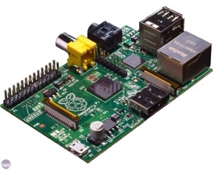
Such a marvelous little computer…
20131015-110724.jpg