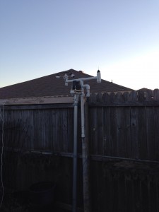
Testing to make sure it’s going to the right server.
Updated Weather Station
Posted by JoeDec 4
Working on updating my weather station currently. It’s been out of commission for a year or so. The rubbermaid box I had it in didn’t last in the elements so I’m having to rethink my mounting process. I’m also looking into getting a larger battery because the 6000 maH one I’m using doesn’t last that long.
I’m also going to be improving it. I’ve put together a circuit to measure how much battery I have left so I can have it turn itself off when the battery is too low. Also have a few more calculations that I can add in to my reporting like heat index which will be useful for the summer.
I’ve also reordered my posts so you will see the updated weather station posts below this one to try to group them in an order of build process
Mast
Posted by JoeDec 12
With this post I wanted to do a full overview of my mast, which I’ve spoken some on before. This will provide instructions on how to build as well as archiving things in case I need to rebuild it in the future. (I just had to re-wire everything and it was pretty difficult remember and figuring out where everything went) The mast is only one part of my weather station; the enclosure, which houses some other sensors as well as the RPi, will be in another post. The way my weather station works is the mast gathers info from the 5 sensors that are contained on/in it via the micro controller. It then sends the data to the Raspberry Pi that resides in the enclosure via I2C to be archived, along with data from the other sensors, within my database tables.
The mast is built out of PVC. This allows me to attach my homemade sensors easily as well as protecting the micro controller that resides inside that runs the sensors.
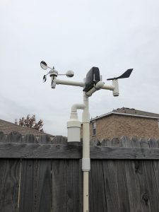
Main Mast Build:
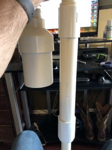
Most of the mast is made from 1″ PVC with different connectors and such. There are a few places in which the 1″ is not used, for example, where the micro controller resides. (You can see it as the larger section). It uses 3/4″ PVC inside 1.5″ PVC. It is built this way to provide some waterproofing for the micro controller. The other section is for the temperature & humidity sensors. It uses some 3″ PVC as a sun shield for the sensors. As for the wiring of the sensors, I will detail that a little later, but all the wiring for the sensors comes together at a point where the larger section starts. It’s there where I “harness” everything together and will detail that later.
Sensors:
As I said, there are 5 sensors within the mast. 3 are sensors I have built myself and two are not. For the sensors I have built myself, I have linked to the posts in which I detail how to build them.
- Wind Vane – Link to post
- Anemometer – Link to post
- Rain Gauge – Link to post
- Temp Sensor – Link to post
- Humidity Sensor – Link to post
Microcontroller & Wiring:
In previous versions of the mast, I have used an Adafruit Trinket board, but when I attempted to add some additional sensors (which failed miserably due to waterproofing) it didn’t have the needed pins required, so I switched to a Arduino Pro Mini 3V. The Pro Mini is slightly larger, more powerful and allows me to power it with 5V coming from the Raspberry Pi.
As I said before, I communicate with the Pro Mini from the RPi via I2C. To do this, I have a cat 5 cable running from the enclosure to the Pro Mini (I only need 4 of the wires, but it’s nice to have a spare 4 in case something happens) and then another piece of cat 5 that runs from the Pro Mini to the wiring harness. I’ll make another post regarding the wiring for the micro controller and the wiring harness as I believe this one has gotten a little long. Link to post
Stay tuned for more…
Anemometer
Posted by JoeAug 9
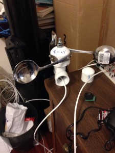
I’ve been meaning to do this for a long time…so without further delay, here is my DIY anemometer.
For those not familiar with what an anemometer is, they are used to measure wind speed. There are certain drawbacks to my design, but after having it active for at least 6 months. I think it works fairly well. The way it works is that it has a reed switch that is triggered with a magnet. In my program, I have it hooked up to an interrupt and count the number of times it triggers within 10 seconds and then plug that into a formula. To come up with this formula, I created a setup on an Arduino that constantly looped the 10 second count. My wife and I took the car out to a county road and did some tests at different speeds. I took the average of 3 tries at 5 different speeds to create the formula I use to convert trigger count to mph.
What you’ll need:
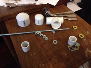
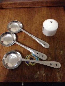
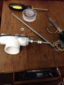
A 7/16″ threaded rod with some nuts and a washer, a 3/4″ to 1″ PVC “T”, a 1 1/2″ PVC cap, a 1″ cap (I think this is the size that fits over one of the sides of the “T”), a slip bushing that will fit in one of the 3/4″ sides of the “T” (that the next item will also fit in), a bearing, 3 ladle spoons (cheap @ Walmart), some small bolts and nuts (I’ll place the size in later), a very small magnet, a reed switch, and some cat 3 (or cat 5) cable.
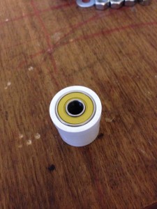
The first step is a bit of work. You have to get the bearing inside the bushing and have it flat with the bushing. What you’ll need to do is sand out the bushing some and use a piece of wood and a clamp to squeeze it in. It’s very important that it is as straight as possible.
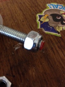
Next we begin to make the shaft. Place a lock nut at one end of your 7/16″ threaded rod.
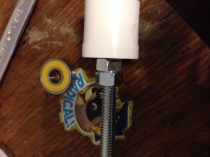
Now place the rod through the bearing so that the lock nut is inside the bushing. On the other end of the threaded bushing, you’ll need two nuts. The first nut will need to hold the rod against the bearing, but not so tight that the rod will not spin. The second nut is to make sure that the first nut doesn’t move. (Work the first nut down to a list past the tightness to the bearing you need, then put the second nut on. Tighten the second nut while loosening the first to get it good and locked.)
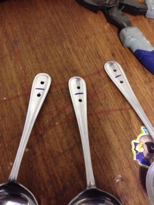
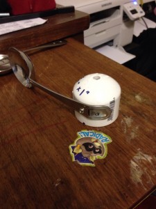
Now comes another difficult part. You’ll need to put a hole for the rod in the exact middle of the 1 1/2″ PVC cap. I think I went through 5 caps before I got it right. (A drill press is your friend). You also need to place two holes in each of the ladles so that your small screws will fit. (These are stainless steel, so go slow! It’s fairly difficult to drill through it) Make sure they are in the center of the handle and that you have the center line marked the same for each spoon. The other piece of this step, you’ll need to bend the handles of the ladles so that they are perpendicular to the ladle. (The come kind of curvy)
Showing the center lines and the bent handles.
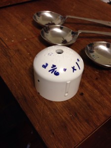
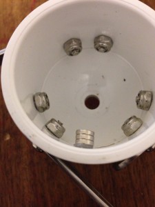
To attach the ladles to the PVC cap, you’ll need to mark and drill 3 holes. They need to be 2 7/16″ from each other and 1″ from the bottom of the cap. (Using a soft sewing tape measure works well for this.
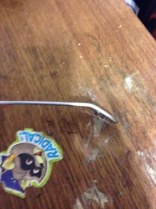
Now here’s where the center line comes in handy. You’ll need to bend the handles of the ladles on this center line as shown.
Now attach the first ladle to the cap and get it level with a table. Mark and drill the hole for the other screw and attach the other side of the ladle to the cap. Continue to do this for the other two ladles. (I used lock nuts to attach these screws.
Hot glue your magnet (or 3) inside the cap.
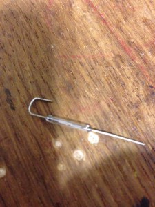
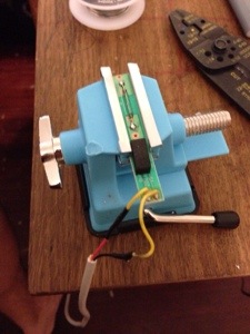
Now for some of the electronics. Take your reed switch and bend one side like shown. Be VERY CAREFUL, these are delicate.
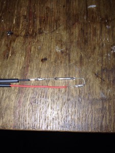
Now solder a wire to each side as shown and place shrink tube over the joints. I have found that you will need water proof this a bit. There are two ways to accomplish this…carefully place shrink tube over the reed switch and seal up the top, or buy these from Sparkfun.
In this step you’ll need to cut your threaded rod to size. Place two nuts (use the locking feature explained earlier) and a washer on the rod and place the cap on. Adjust the nuts so that the magnet would pass over the reed switch when shown attached above. Give yourself enough room on top side of the cap to place two more nuts on and cut the rod with a hacksaw. Be careful not to mess up the threads. (Too much). Next use hot glue to attach the reed switch and wire as shown. Almost Done!
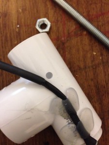
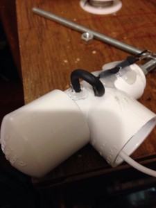
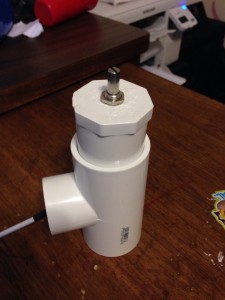
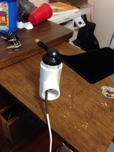
Finishing up, drill a hole in the side of the “T” so the wire can go back inside. Hot glue around the wire to keep it still. You can use 1″ PVC to connect it to the other parts of the weather station. (as shown in the following picture..) Place the cap on the underside of the “T” to keep things out. Here is a finished version on the desk and attached to the “mast”. I will post the python (and now Trinket as I’ll go into later) code that use later.
Wind Direction Sensor
Posted by JoeAug 11
This is one of the easiest sensors I’ve built. Basically it is a 10k 360 degree potentiometer with a wind vane attached to the top. I set North equal to 0 resistance and then record the values through testing at the other directions and then split the difference between them. (Will explain this more when I do the coding part)
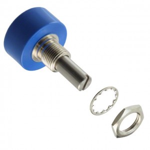
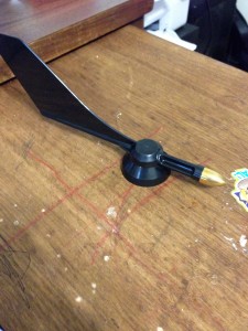
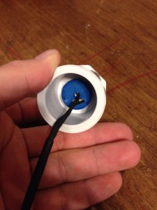
Here are the two main parts to the sensor. A Bourns 6639S-1-103 10k rotary potentiometer and a Davis instruments wind vane with brass tip for Vantage Pro2 anemometer. You’ll also need some cat3 or cat 5 cable, a 1 1/4″ to 1″ PVC “T” and two 1 1/4″ PVC plug.
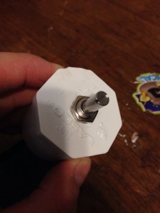
First you want to drill a hole in the middle of the PVC plug for the pot to go through. (Make sure you can get all the threads through the hole).
Before you tighten the pot into the hole, you’ll need to solder some wires to the bottom of the pot. For the Raspberry Pi, you only need one on peg 1 and one on peg 2 (Power on peg 1 & read on peg 2). For Arduino, You’ll need to attach a ground to peg 3 of the pot. Make sure and use some shrink wrap to protect the joints.
Once your soldering is done, tighten down the pot into the hole and slip your wire through the “T”. Make sure you mark “N” on your plug where 0 resistance is read after the pot is tightened down. Keep your pot adjusted to this position. Slide the plug into the T. (Place another 1 1/4″ plug in the other side).
Finally, you’ll need to attach the vane. The vane has a small Allen screw in it. You’ll need to loosen it up before you slide the vain onto the post of the pot. Adjust the vane so it’s just barely off the plug, point it towards “N” that you marked on the plug and tighten it down.
As far as wiring this sensor, the wire soldered to peg 1 should go to +v, the wire soldered to peg 2 should go to either an read spot on your ADC (if you’re using a Pi, something like the MCP3008) or to an analog read pin on your Arduino, and the wire on peg 3 should go to ground (if it’s connected)
I’ll share the reading code part later when I can get on my main computer at home.
Wind Direction Reading
Posted by JoeAug 11
As I stated in the previous post, the readings of this sensor take a lot of work to setup. You have to get a reading at each direction and then split the difference between them to get a high and low. Somewhere I have an excel file that I use to do all the calculations and print out the code. I’ll load it here if/when I find it.
To use this, you will need to place an include in your python program:
from wind_dir import wind_dir
Then when you want to get the value, you call the function with your ADC reading:
wind_direction = wind_dir(wind_dir_read)
The annoying part of this is setting up this file. All it does is take your reading and see where it falls within the table of max & min values established through testing:
#!/usr/bin/env python
wind_dir_high_NNE=962
wind_dir_high_NE=937
wind_dir_high_ENE=885
wind_dir_high_E=839
wind_dir_high_ESE=798
wind_dir_high_SE=760
wind_dir_high_SSE=726
wind_dir_high_S=695
wind_dir_high_SSW=667
wind_dir_high_SW=641
wind_dir_high_WSW=616
wind_dir_high_W=593
wind_dir_high_WNW=571
wind_dir_high_NW=550
wind_dir_high_NNW=535
wind_dir_low_NNE=935
wind_dir_low_NE=884
wind_dir_low_ENE=838
wind_dir_low_E=797
wind_dir_low_ESE=759
wind_dir_low_SE=725
wind_dir_low_SSE=694
wind_dir_low_S=666
wind_dir_low_SSW=640
wind_dir_low_SW=615
wind_dir_low_WSW=592
wind_dir_low_W=570
wind_dir_low_WNW=549
wind_dir_low_NW=534
wind_dir_low_NNW=527
def wind_dir(amt):
if amt <= wind_dir_high_NNE and amt >= wind_dir_low_NNE:
wind_direction = 'NNE'
elif amt <= wind_dir_high_NE and amt >= wind_dir_low_NE:
wind_direction = 'NE'
elif amt <= wind_dir_high_ENE and amt >= wind_dir_low_ENE:
wind_direction = 'ENE'
elif amt <= wind_dir_high_E and amt >= wind_dir_low_E:
wind_direction = 'E'
elif amt <= wind_dir_high_ESE and amt >= wind_dir_low_ESE:
wind_direction = 'ESE'
elif amt <= wind_dir_high_SE and amt >= wind_dir_low_SE:
wind_direction = 'SE'
elif amt <= wind_dir_high_SSE and amt >= wind_dir_low_SSE:
wind_direction = 'SSE'
elif amt <= wind_dir_high_S and amt >= wind_dir_low_S:
wind_direction = 'S'
elif amt <= wind_dir_high_SSW and amt >= wind_dir_low_SSW:
wind_direction = 'SSW'
elif amt <= wind_dir_high_SW and amt >= wind_dir_low_SW:
wind_direction = 'SW'
elif amt <= wind_dir_high_WSW and amt >= wind_dir_low_WSW:
wind_direction = 'WSW'
elif amt <= wind_dir_high_W and amt >= wind_dir_low_W:
wind_direction = 'W'
elif amt <= wind_dir_high_WNW and amt >= wind_dir_low_WNW:
wind_direction = 'WNW'
elif amt <= wind_dir_high_NW and amt >= wind_dir_low_NW:
wind_direction = 'NW'
elif amt <= wind_dir_high_NNW and amt >= wind_dir_low_NNW:
wind_direction = 'NNW'
else:
wind_direction = 'N'
return wind_direction
As you can see from the above, I get all the way down to the minor directions such as “NNE” & “ESE”, etc. You can change it to suit your needs.
Rain Gauge
Posted by JoeNov 30
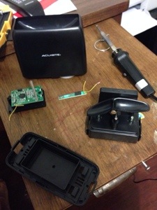
The rain gauge to me was one of the easiest to do, mostly because I kind of cheated a bit. Since I didn’t think I could create a sensor for cheaper than I could buy one, I spent $20 and bought the Acu-Rite gauge at Wal-Mart and modified it to my needs.
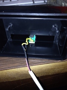
To start off, you’ll need to take apart the “gauge” piece and set the wireless display aside. This is fairly easy, as the main cover and tipping part comes off fairly easy. Next, you’ll need to remove the screws under the battery compartment to remove the circuit board. There are two wires coming out of the circuit board that go to the reed switch within the gauge that need to be clipped.
The reed switch is set within the tipping part, so carefully pull it out and strip the wires. You’ll need to attach wires to each of these. I use some telephone cable/cat3. I usually start with attaching about 10 feet of wire just in case. When attaching, make sure you solder the wires and use shrink tube to protect the connection.
Next, carefully slide the reed switch back into the tipping piece. Real quick explanation of how this works….A reed switch “closes” when a magnetic field is near. So we run current through the reed switch and place a magnet in the tipping mechanism to pass over the reed switch when it tips. When rain fills up a side of the gauge it tips over and the magnet causes the reed switch to complete the circuit for a brief period, which we can count….
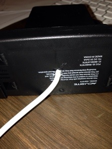
We then need to drill a hole in the battery compartment and in the bottom piece to allow the wire to go through. Make sure to put a little hot glue in the hole in the bottom to protect against the elements a bit.
For testing, plug the two wires into a breadboard, one needs to run to power and the other to one of the pins on the Raspberry Pi (I believe I use number 17). In order to count how many times the gauge tips, we have to use GPIO interrupts. Before I forget, each tip is .02 inches of rain….
To keep count, I use a script that runs when the Pi starts up and monitors that pin. When the gauge tips and it detects a voltage “spike” it opens a file, takes the number, adds 1 to it and then rewrites the file with that number. (When I run the script that gets the current weather, I access this file and multiply by .02) At midnight every night, I also run a script that resets the number in the file to 0.
Here is the file I use to monitor the pin…
#!/usr/bin/env python2.7
import time
import os
import RPi.GPIO as GPIO
GPIO.setmode(GPIO.BCM)
First bit is to set up the normal stuff…I have to give some credit to Alex Eames @ http://RasPi.tv/ for the pieces of interrupt code. http://raspi.tv/2013/how-to-use-interrupts-with-python-on-the-raspberry-pi-and-rpi-gpio
# GPIO 17 set up as input. It is pulled up to stop false signals

GPIO.setup(17, GPIO.IN, pull_up_down=GPIO.PUD_DOWN)
Next we need to set up the pin for interrupts. We’re setting up pin 17 as an input and using an internal resistor to pull it down to 0 when there is no current.
def my_callback(channel):

	tfile = open("/home/pi/rain_count.txt")

	text = tfile.readline()

	tfile.close()
rain_count = int(text)
rain_count += 1
tfile = open("/home/pi/rain_count.txt", "w")
tfile.write(str(rain_count))
tfile.close()
Now we create the function that gets called when a “spike” is detected. This function opens the file called “rain_count.txt” and reads the number, adds one and then writes the new number to the file. When doing this, don’t forget to create the rain_count.txt file prior to running this and place a 0 in it.
GPIO.add_event_detect(17, GPIO.RISING, callback=my_callback, bouncetime=300)
Now we add the interrupt event that monitors pin 17 and says that we want to monitor it for a rising event (I call a spike). When it is detected it calls the function “my_callback” and then waits 300 milliseconds before it will try to detect another one. (The bounce time is necessary to keep from getting false positives.)
while True:

	time.sleep(60)
The last bit is just an infinite loop to keep the script running. To run this at startup of the Pi, you’ll need to add a line to the crontab file:
@reboot python /home/pi/rain-gauge.py &
The clearing file is fairly easy too….
#!/usr/bin/env python2.7

import time

import os
tfile = open("/home/pi/rain_count.txt", "w")
rain_count = 0
tfile.write(str(rain_count))
tfile.close()
And add this to your crontab file to run at midnight…
* 0 * * * /home/pi/rain-clear.py
The last bit is grabbing the count when you run the the weather script…
#get rain amount

rain_file = open("/home/pi/rain_count.txt")

rain_gauge = rain_file.readline()

rain_file.close()
rain_count = int(rain_gauge)
rain_count =float(rain_count) * .02
rain_count = round(rain_count, 1)
The only thing I’ll mention here since it’s pretty straight forward is that you’ll notice I do a round at the end. I’ve experienced some false positives during the day when it’s sunny (usually 1 or 2 a day), so I just get rid of them by rounding to the nearest 10th.
Mast – Temp & Humidity Sensors
Posted by JoeDec 12
To start off, I wanted to say that I know there are other sensors that can do what the sensors that I use can do and possibly even do it better, but I’ve had these two sensors for several years now and they have done exactly what I’ve needed them to without fail.
For temperature I use a DS18B20 and for humidity I use a Honeywell HIH-5031. The DS18B20 is a very popular temperature sensor which uses the 1 wire protocol. the HIH-5031 is an analog humidity sensor that runs on 3V. The DS18B20 outputs a temp in C with the Arduino code, but the HIH-5031 only outputs a voltage which requires some code to translate into humidity. I’ll post all of that later when I post about the code I use on the Raspberry Pi.
Sensor Wiring:
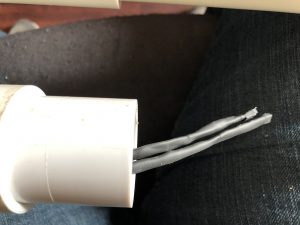
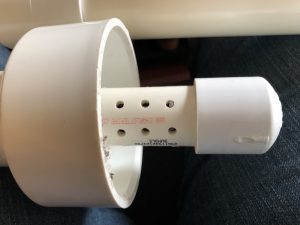
For wiring these sensors, each has 3 pins, a power, ground & read pin. Because each sensor really needs to be exposed to air to reach correctly, I soldered several single wires to their pins and then used shrink tube to cover the connections and then another piece of shrink tube to collect the 3 wires together and cover a bit of the end of the sensor. (You can see this in the pic above) The two sets of 3 wires are brought together into a single cat 3 cable (4 wires). I wire the power of each sensor to a red wire, the ground of each sensor to a black wire, then the read pins of each sensor to it’s own wire. This allows me to be able to have only 4 wires in the wiring harness for these two sensors instead of 6.
Sensor Mounting:
As you can see above, I use an offshoot of my main mast to hold these two sensors. The sensors themselves sit within a piece of 1 inch PVC that has holes drilled in it to allow for air flow. This is covered with a 3″ PVC pipe that protects from solar radiation as well as rain. I don’t have many of the details on all the PVC connections I used to make this happen, but all I did was go to the hardware store and start piecing things together to get what I wanted.
Mast – Microcontroller & Wiring Harness
Posted by JoeDec 12
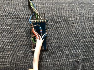
In a previous post I mentioned that I would make a separate post regarding the micro controller wiring as well as the wiring harness. Again, for the micro controller I am using an Arduino Pro Mini 3V. Link to code Below are a few pics and wiring details:
Microcontroller Pics:
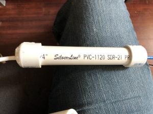
A few pics of the micro controller wiring and waterproofing tube. As you can see in the below pic, the micro controller sits within some 3/4″ PVC with caps on each end that have holes for the wires to come out of. My suggestion would be to make the “top” hole waterproof by putting silicon or something around the cat 5 cable coming out and leave the bottom one free to slide in case you need to get to your micro controller for repair reasons.
Micro Controller Wiring:
I’ll include the micro controller pin as well as the wire color and “direction” of wire in this format: Pin on Pro Mini – Wire/direction – (wire color.) (Some will have multiple wires attached)
- Raw – 5V from RPi – (blue)
- GND – GND from RPi – (blue-white)
- A4 – SDA from RPi – (green)
- A5 – SCL from RPi – (green-white)
- Vcc
- Power to wiring harness – (brown)
- 4.7k Ω resistor for DS18B20 to Pin 10
- GND
- Ground to wiring harness – (orange)
- Ground to wiring harness – (brown-white)
- 65k Ω resistor for HIH-5031 to Pin A2
- A1 – read pin for wind vane in wiring harness – (green)
- A2
- read pin for HIH-5031 in wiring harness – (orange-white)
- 65k Ω resistor for HIH-5031 to GND
- D2 – interrupt for rain gauge in wiring harness – (blue-white)
- D3 – interrupt for anemometer in wiring harness – (blue)
- D10
- read pin for DS18B20 in wiring harness – (green-white)
- 4.7k Ω resistor for DS18B20 to Vcc
Wiring Harness Pics & Wiring:
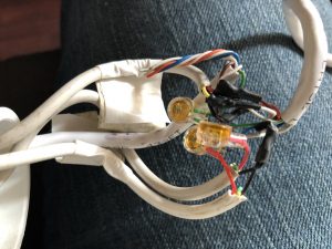
The wiring harness is where all the wires from the sensors come together with the wire coming from the Pro Mini. I solder the wires together and use shrink tube to protect them, but I ran out of shrink tube and had to use these other connectors…don’t use these connectors. It’s a mess…
For the wiring, I’ll list the wire color coming out of the micro controller and what wires are attached to it from the sensors.
- Brown-white
- GND for rain gauge
- GND for anemometer
- Brown
- These two are tied together and I’ll explain in another post
- 3V for DS1B20
- 3V for HIH-5031
- 3V for wind vane
- These two are tied together and I’ll explain in another post
- Blue-white
- 3V for rain gauge
- Blue
- 3V for anemometer
- Green-white
- read pin for DS18B20
- Green
- read pin for wind vane
- Orange-white
- read pin for HIH-5031
- Orange
- These two are tied together and I’ll explain in another post
- GND for DS1B20
- GND for HIH-5031
- GND for wind vane
- These two are tied together and I’ll explain in another post
Mast – Micro controller code
Posted by JoeDec 12
Below is the arduino code I use for the Pro Mini. I’m going to post it in block quotes as well as a link to a txt file with the code. I feel that it’s commented well so I’m not going to go into details here. It uses the standard Wire, OneWire & AVR/Interrupt libraries as well as some found code for the DS18B20 reading. I’m planning on loading all my code to Github in the future so it’s all in one place. I just have to figure out how to do that appropriately. (Since some of the libraries I use for sensors come from other sources, ie: Adafruit)
#include <Wire.h>
#include <avr/interrupt.h>
#include <OneWire.h>// defining which I2C addres to use
#define SLAVE_ADDRESS 0x05
// setting he number used to request data from pro mini to send back to the pi
int number = 0;//setting up pins for sensors
const byte rainGauge = 2;
const byte windSpeed = 3;// setting up variables for sensors
volatile int rainCount = 0;
volatile int windCount = 0;
volatile int windCountSend = 0;
volatile int windCountSendMax = 0;
long rainDebouncingTime = 300; //Debouncing Time in Milliseconds
volatile unsigned long rainLastMicros;
long windDebouncingTime = 100; //Debouncing Time in Milliseconds
volatile unsigned long windLastMicros;
volatile int windDir = 0;int temp = 0;
// pin for DS18B20
OneWire ds(10); // on pin 10void setup() {
// initialize i2c as slave
Wire.begin(SLAVE_ADDRESS);// define callbacks for i2c communication
Wire.onReceive(receiveData);
Wire.onRequest(sendData);// setup pins for sensors and attach interrupts
pinMode(rainGauge, INPUT);
digitalWrite (rainGauge, HIGH); // internal pull-up resistor
attachInterrupt (0, debounceRain, FALLING); // attach interrupt handler
pinMode(windSpeed, INPUT);
digitalWrite (windSpeed, HIGH); // internal pull-up resistor
attachInterrupt (1, debounceWind, FALLING); // attach interrupt handler
Serial.begin(9600);}
void loop() {
//***********************************
// Read DS18B20
int HighByte, LowByte, TReading, SignBit, Tc_100, Whole, Fract;byte i;
byte present = 0;
byte data[12];
byte addr[8];if ( !ds.search(addr)) {
ds.reset_search();
return;
}ds.reset();
ds.select(addr);
ds.write(0x44,1); // start conversion, with parasite power on at the enddelay(1000); // maybe 750ms is enough, maybe not
// we might do a ds.depower() here, but the reset will take care of it.present = ds.reset();
ds.select(addr);
ds.write(0xBE); // Read Scratchpadfor ( i = 0; i < 9; i++) { // we need 9 bytes
data[i] = ds.read();}
LowByte = data[0];
HighByte = data[1];
TReading = (HighByte << 8) + LowByte;
SignBit = TReading & 0x8000; // test most sig bit
if (SignBit) // negative
{
TReading = (TReading ^ 0xffff) + 1; // 2’s comp
}
Tc_100 = (6 * TReading) + TReading / 4; // multiply by (100 * 0.0625) or 6.25temp = Tc_100;
//************************************
// get wind speed
windCount = 0;
delay(10000);
windCountSend = windCount;
if (windCountSend > windCountSendMax){
windCountSendMax = windCountSend;
}}
// callback for received data
void receiveData(int byteCount){while(Wire.available()) {
number = Wire.read();
// setup to reset rain count. R-Pi sends this at midnight to reset
if (number == 8){
rainCount = 0;
}}
}// callback for sending data
void sendData(){
byte sendData[2];
int sendVal = 0;
if (number == 1){
sendVal = rainCount;}
// wind speed
else if (number == 2){
sendVal = windCountSend;}
// wind direction
else if (number == 3){
sendVal = analogRead(1);
}
// wind gust speed
else if (number == 4){
sendVal = windCountSendMax;
windCountSendMax = 0;}
// temperature
else if (number == 5){
sendVal = temp;
}
// humidity
else if (number == 6){
sendVal = analogRead(2);
}else {
sendVal = number;
}
// sending requested data to the Pi
sendData[0] = (byte) sendVal & 0xFF;
// Serial.println(sendData0, HEX);
sendData[1] = (byte) (sendVal >> 8) & 0xFF;
// Serial.println(sendData1, HEX);
Wire.write(sendData, 2);
//Wire.write(sendData0);
//Wire.write(sendData1);
}// debouncing of interrupt sensors so only count once per action
void debounceRain() {
if((long)(micros() – rainLastMicros) >= rainDebouncingTime * 1000) {
rainFunc();
rainLastMicros = micros();
}
}void debounceWind() {
if((long)(micros() – windLastMicros) >= windDebouncingTime * 1000) {
windFunc();
windLastMicros = micros();
}
}// incrementing the variables used for counting sensors
void rainFunc() {
rainCount++;
Serial.print(rainCount);
}void windFunc() {
windCount++;
Serial.println(windCount);
}
