Archive for August, 2014

Anemometer

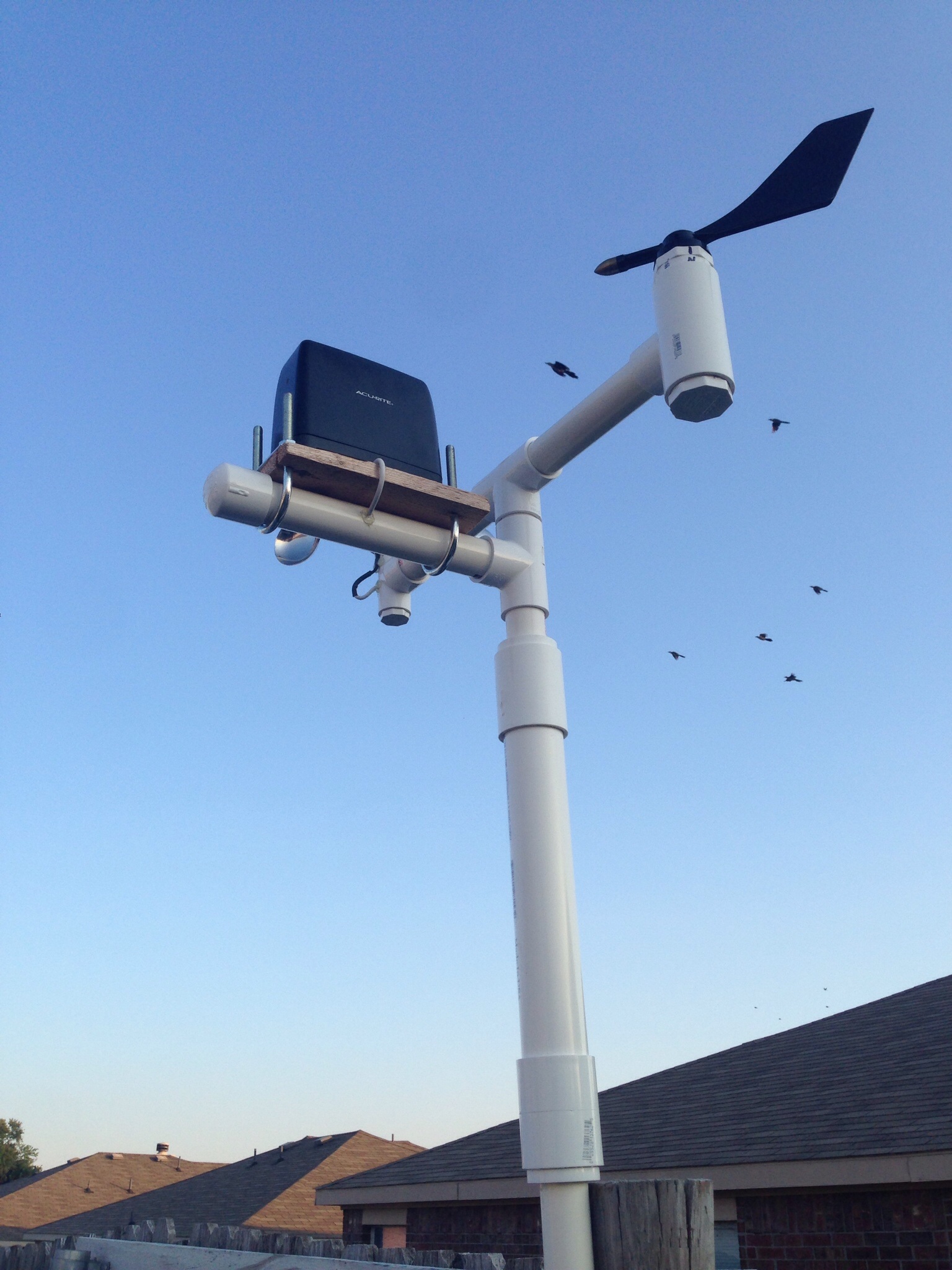
I’ve been meaning to do this for a long time…so without further delay, here is my DIY anemometer.

For those not familiar with what an anemometer is, they are used to measure wind speed. There are certain drawbacks to my design, but after having it active for at least 6 months. I think it works fairly well. The way it works is that it has a reed switch that is triggered with a magnet. In my program, I have it hooked up to an interrupt and count the number of times it triggers within 10 seconds and then plug that into a formula. To come up with this formula, I created a setup on an Arduino that constantly looped the 10 second count. My wife and I took the car out to a county road and did some tests at different speeds. I took the average of 3 tries at 5 different speeds to create the formula I use to convert trigger count to mph.

What you’ll need:

IMG_0029.JPG

A 7/16″ threaded rod with some nuts and a washer, a 3/4″ to 1″ PVC “T”, a 1 1/2″ PVC cap, a 1″ cap (I think this is the size that fits over one of the sides of the “T”), a slip bushing that will fit in one of the 3/4″ sides of the “T” (that the next item will also fit in), a bearing, 3 ladle spoons (cheap @ Walmart), some small bolts and nuts (I’ll place the size in later), a very small magnet, a reed switch, and some cat 3 (or cat 5) cable.

IMG_0026.JPG

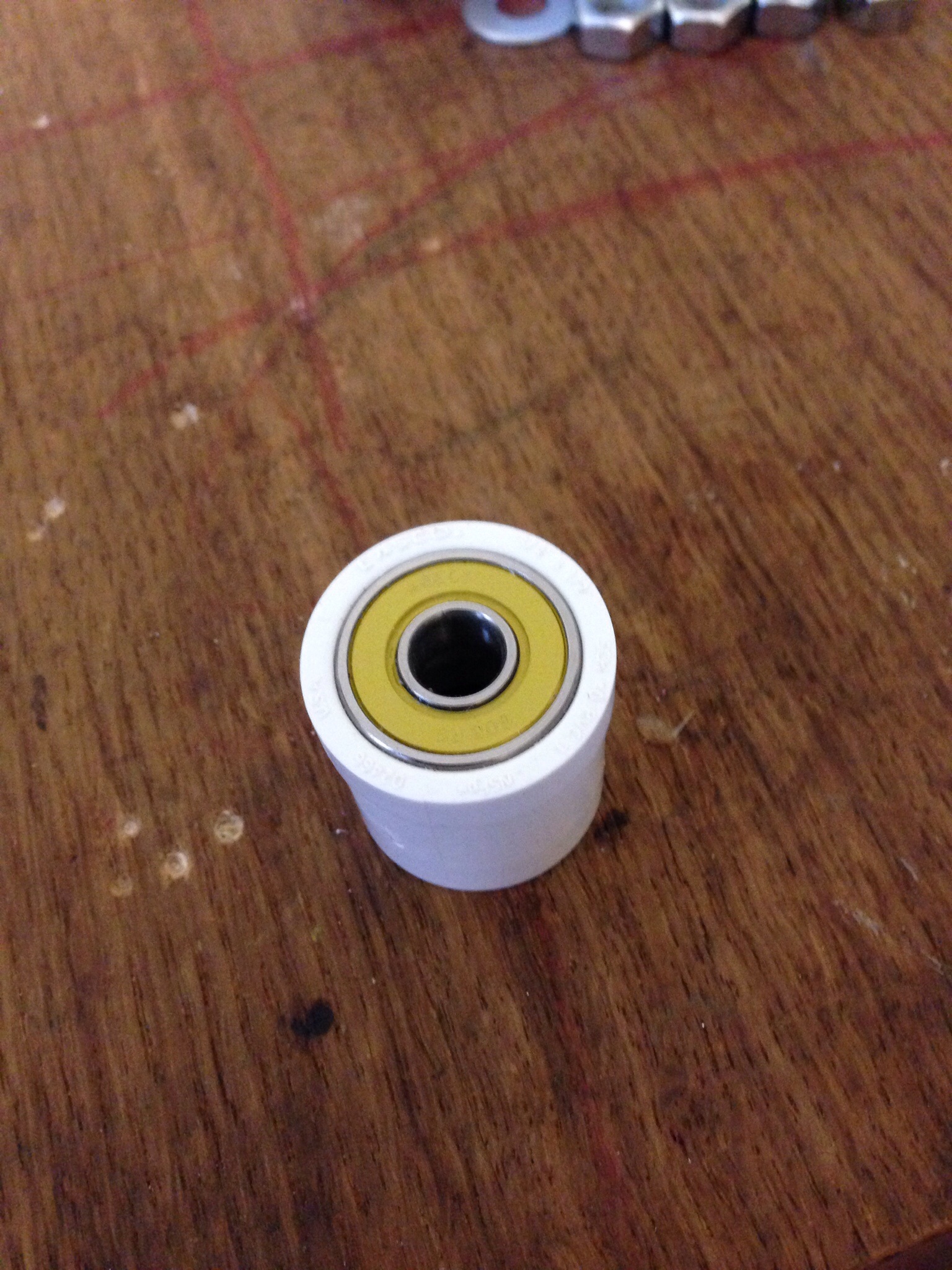
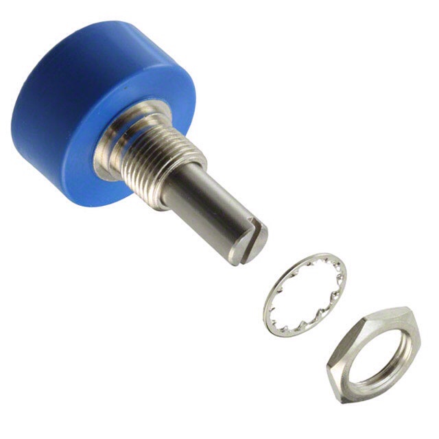
The first step is a bit of work. You have to get the bearing inside the bushing and have it flat with the bushing. What you’ll need to do is sand out the bushing some and use a piece of wood and a clamp to squeeze it in. It’s very important that it is as straight as possible.

IMG_0028.JPG

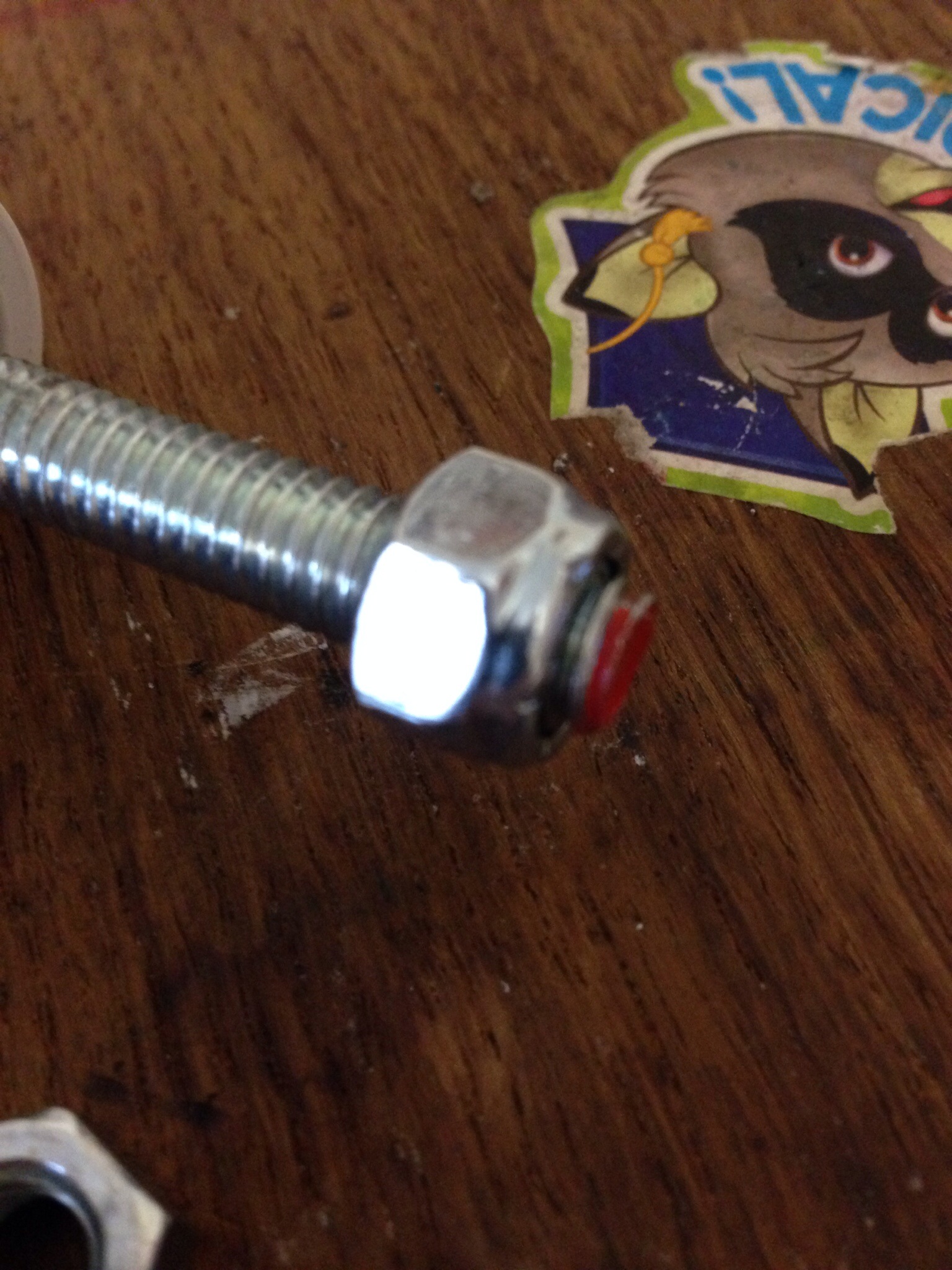
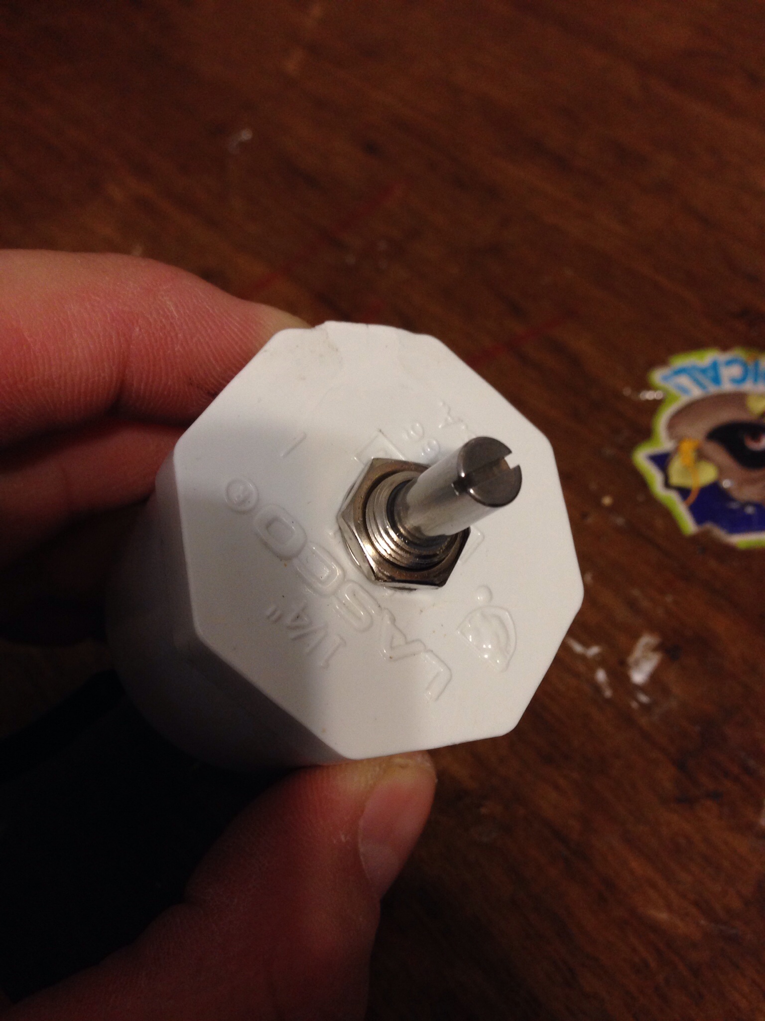
Next we begin to make the shaft. Place a lock nut at one end of your 7/16″ threaded rod.

IMG_0031.JPG

Now place the rod through the bearing so that the lock nut is inside the bushing. On the other end of the threaded bushing, you’ll need two nuts. The first nut will need to hold the rod against the bearing, but not so tight that the rod will not spin. The second nut is to make sure that the first nut doesn’t move. (Work the first nut down to a list past the tightness to the bearing you need, then put the second nut on. Tighten the second nut while loosening the first to get it good and locked.)

IMG_0034.JPG

Now comes another difficult part. You’ll need to put a hole for the rod in the exact middle of the 1 1/2″ PVC cap. I think I went through 5 caps before I got it right. (A drill press is your friend). You also need to place two holes in each of the ladles so that your small screws will fit. (These are stainless steel, so go slow! It’s fairly difficult to drill through it) Make sure they are in the center of the handle and that you have the center line marked the same for each spoon. The other piece of this step, you’ll need to bend the handles of the ladles so that they are perpendicular to the ladle. (The come kind of curvy)

IMG_0036.JPG

IMG_0027.JPG

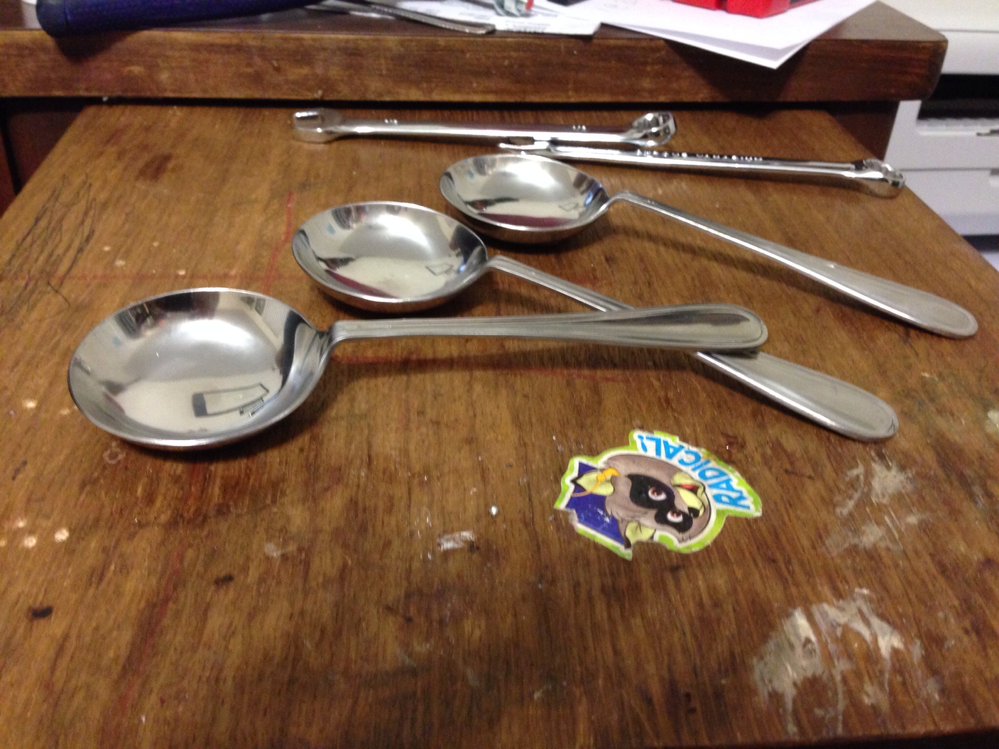
Showing the center lines and the bent handles.

IMG_0037.JPG

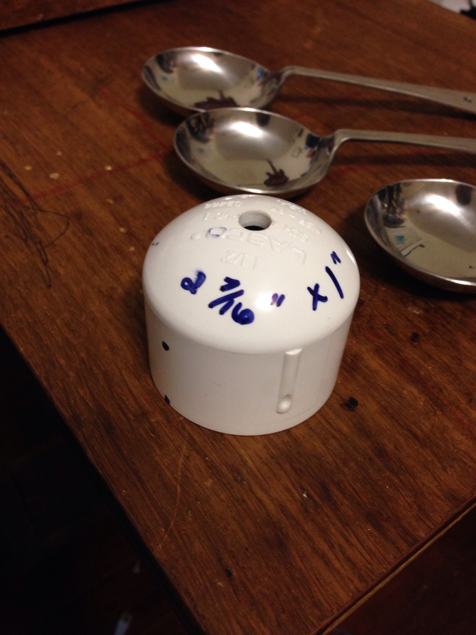
To attach the ladles to the PVC cap, you’ll need to mark and drill 3 holes. They need to be 2 7/16″ from each other and 1″ from the bottom of the cap. (Using a soft sewing tape measure works well for this.

IMG_0032.JPG

Now here’s where the center line comes in handy. You’ll need to bend the handles of the ladles on this center line as shown.

IMG_0033.JPG

Now attach the first ladle to the cap and get it level with a table. Mark and drill the hole for the other screw and attach the other side of the ladle to the cap. Continue to do this for the other two ladles. (I used lock nuts to attach these screws.

IMG_0035.JPG

Hot glue your magnet (or 3) inside the cap.

IMG_0038.JPG

Now for some of the electronics. Take your reed switch and bend one side like shown. Be VERY CAREFUL, these are delicate.

IMG_0039.JPG

Now solder a wire to each side as shown and place shrink tube over the joints. I have found that you will need water proof this a bit. There are two ways to accomplish this…carefully place shrink tube over the reed switch and seal up the top, or buy these from Sparkfun.

IMG_0042.JPG

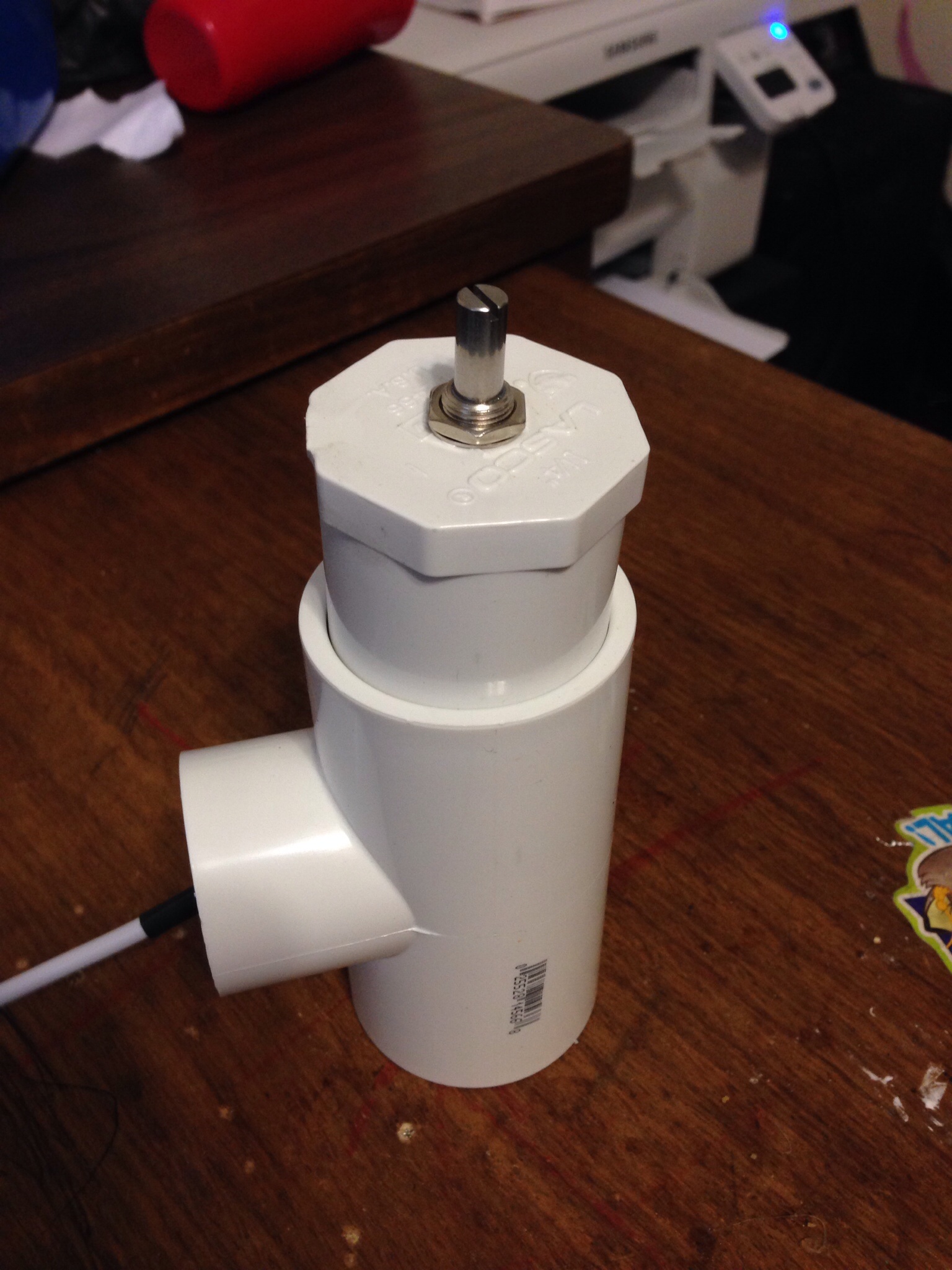
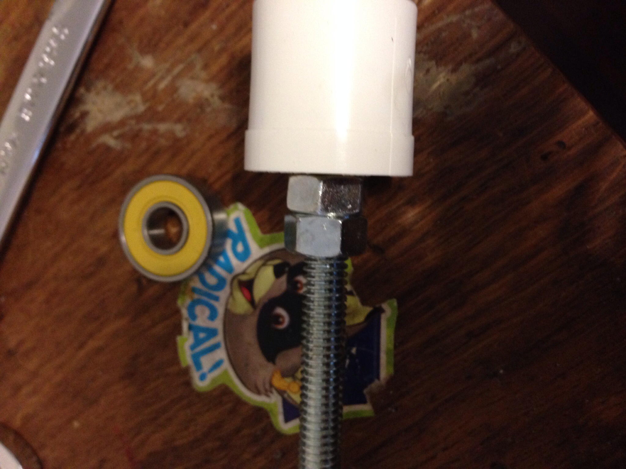
In this step you’ll need to cut your threaded rod to size. Place two nuts (use the locking feature explained earlier) and a washer on the rod and place the cap on. Adjust the nuts so that the magnet would pass over the reed switch when shown attached above. Give yourself enough room on top side of the cap to place two more nuts on and cut the rod with a hacksaw. Be careful not to mess up the threads. (Too much). Next use hot glue to attach the reed switch and wire as shown. Almost Done!

IMG_0045.JPG

IMG_0044.JPG

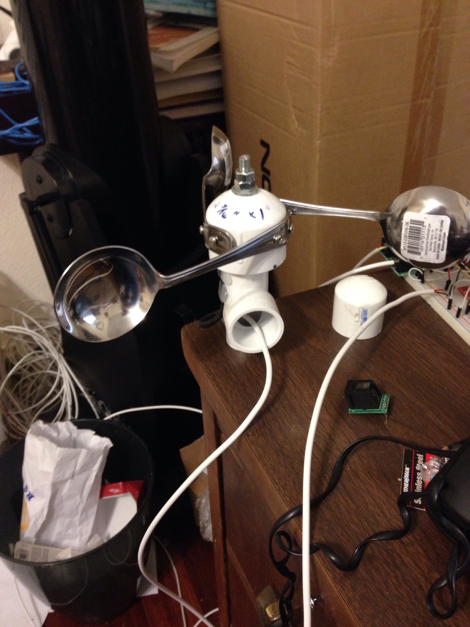
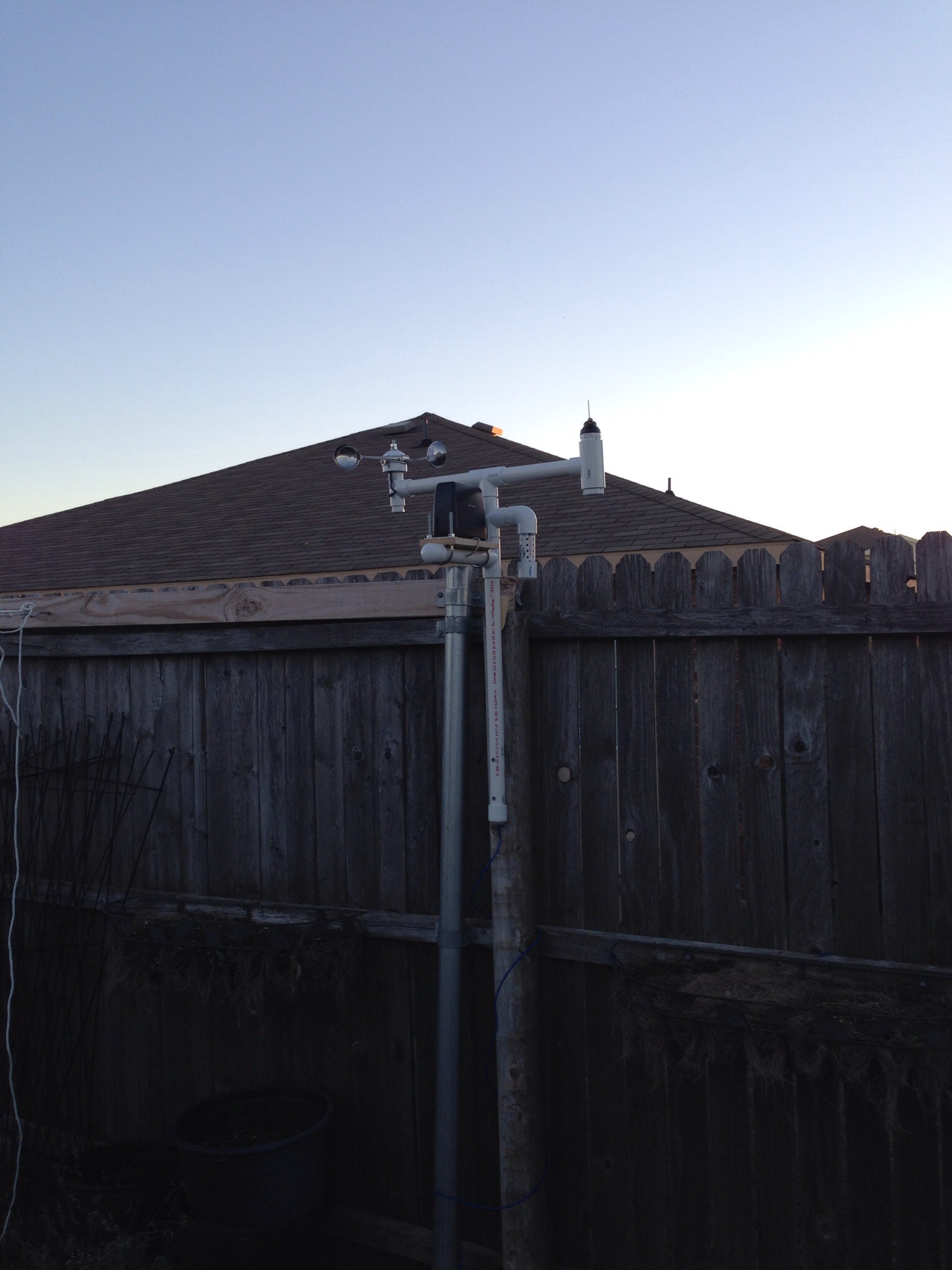
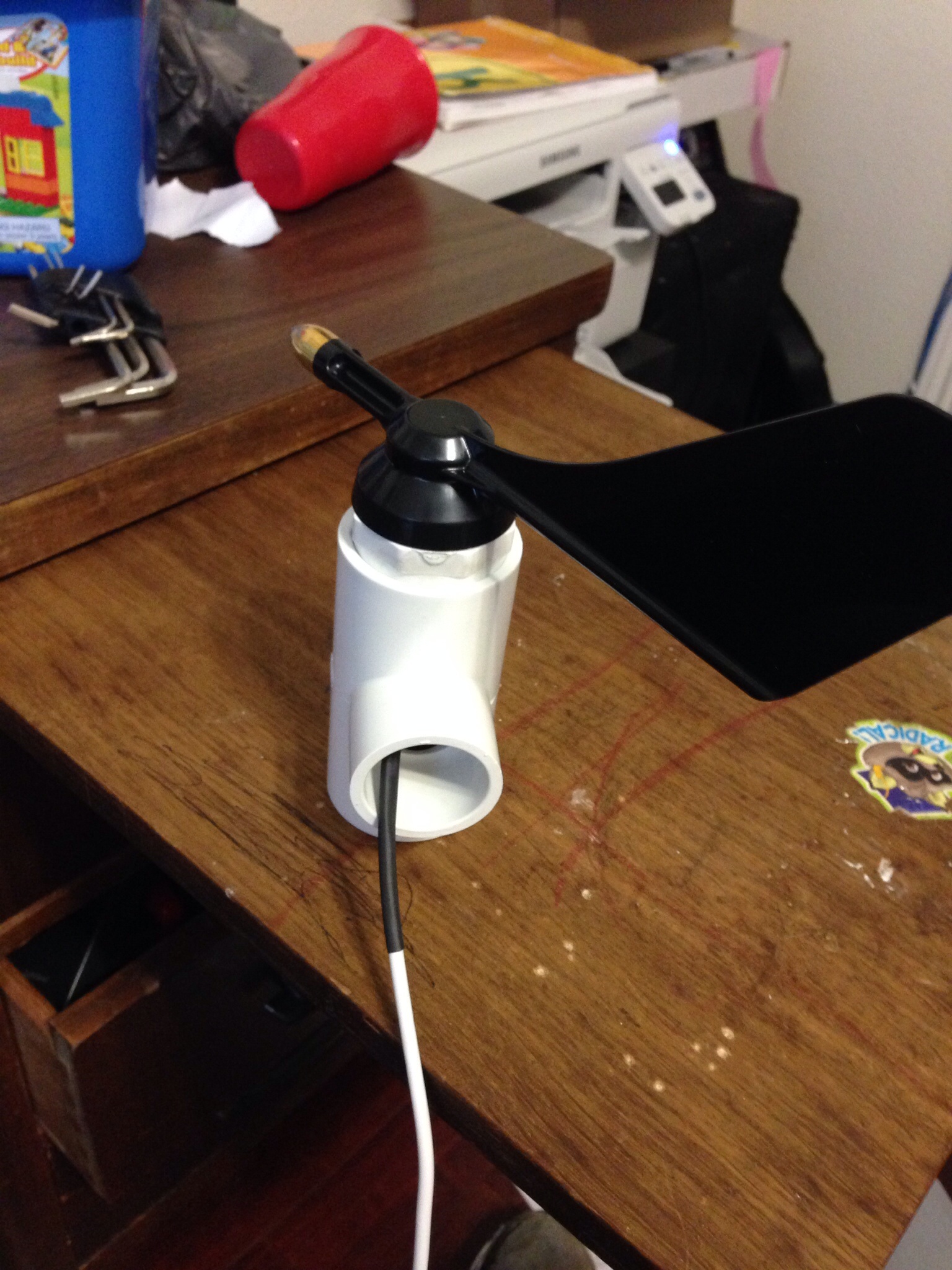
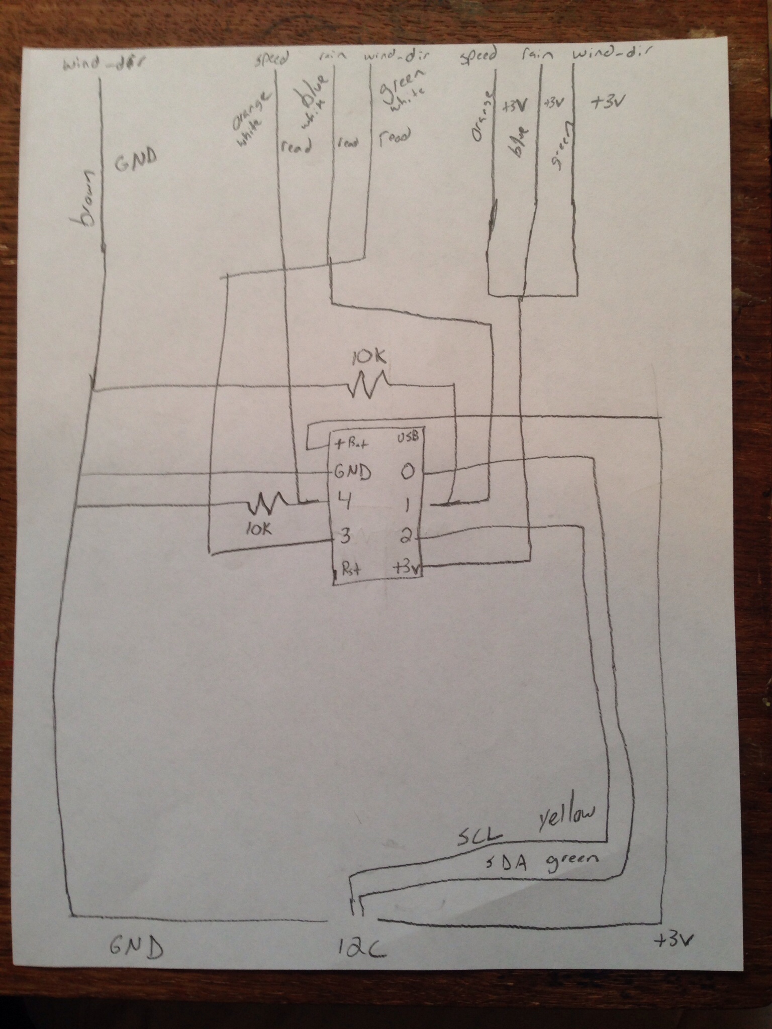
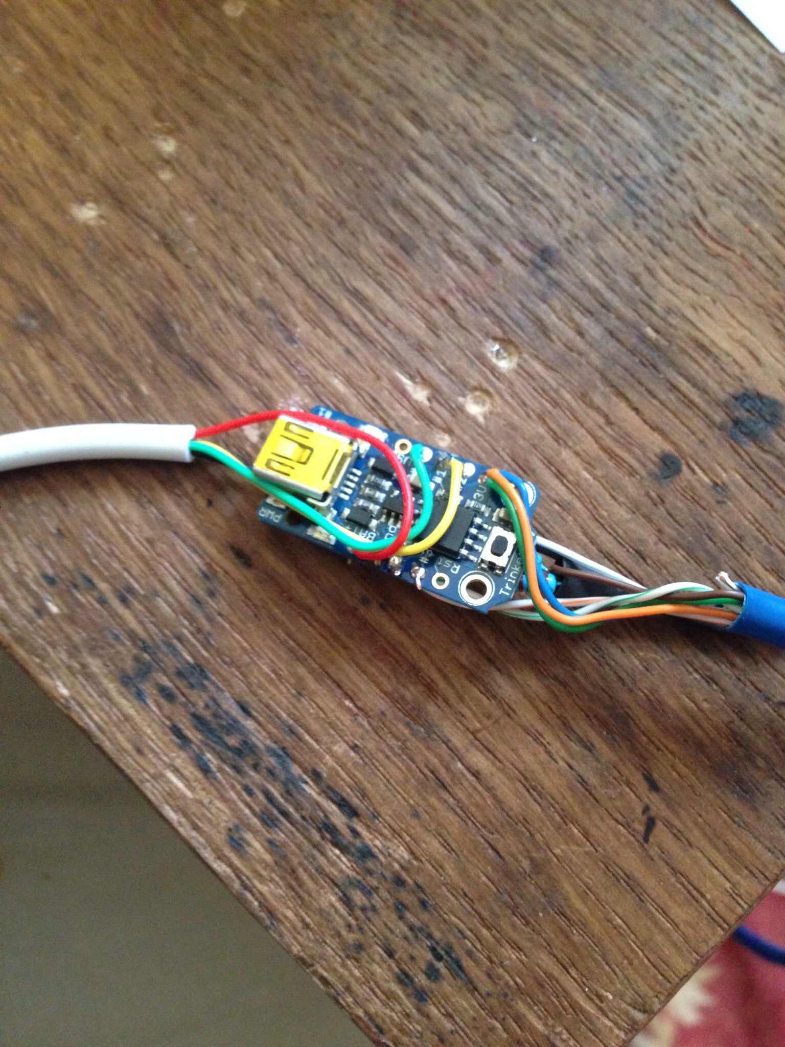
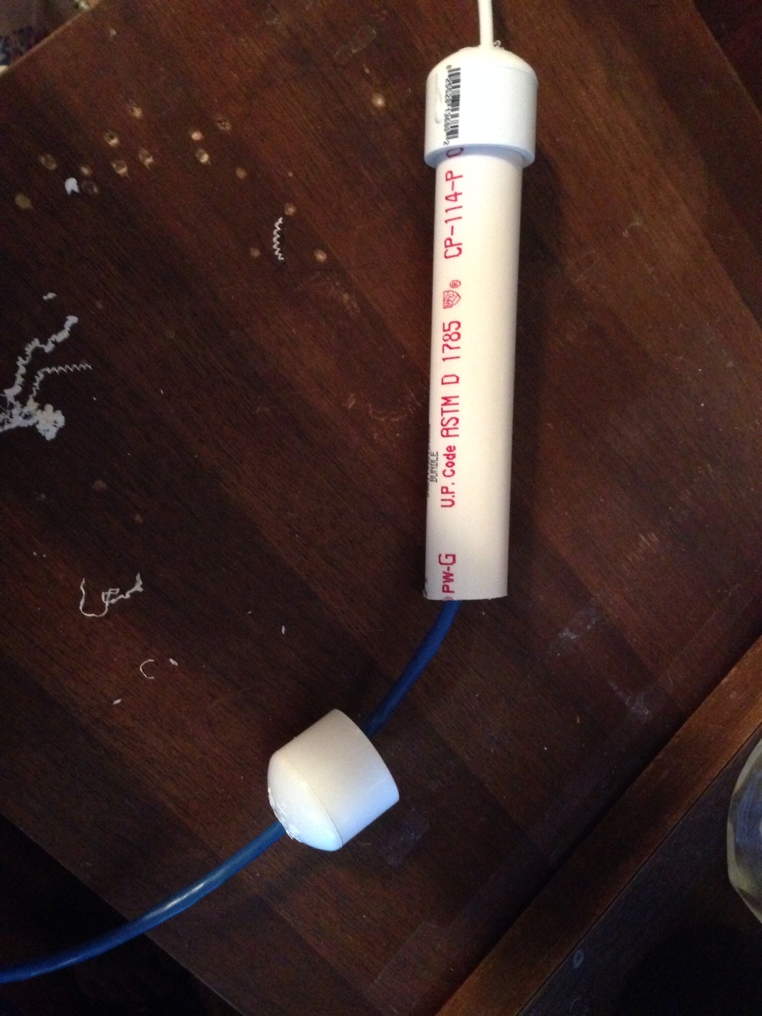
Finishing up, drill a hole in the side of the “T” so the wire can go back inside. Hot glue around the wire to keep it still. You can use 1″ PVC to connect it to the other parts of the weather station. (as shown in the following picture..) Place the cap on the underside of the “T” to keep things out. Here is a finished version on the desk and attached to the “mast”. I will post the python (and now Trinket as I’ll go into later) code that use later.

IMG_0046.JPG

IMG_0047.JPG

Wind Direction Sensor

This is one of the easiest sensors I’ve built. Basically it is a 10k 360 degree potentiometer with a wind vane attached to the top. I set North equal to 0 resistance and then record the values through testing at the other directions and then split the difference between them. (Will explain this more when I do the coding part)

image

image

Here are the two main parts to the sensor. A Bourns 6639S-1-103 10k rotary potentiometer and a Davis instruments wind vane with brass tip for Vantage Pro2 anemometer. You’ll also need some cat3 or cat 5 cable, a 1 1/4″ to 1″ PVC “T” and two 1 1/4″ PVC plug.

image

First you want to drill a hole in the middle of the PVC plug for the pot to go through. (Make sure you can get all the threads through the hole).

image

Before you tighten the pot into the hole, you’ll need to solder some wires to the bottom of the pot. For the Raspberry Pi, you only need one on peg 1 and one on peg 2 (Power on peg 1 & read on peg 2). For Arduino, You’ll need to attach a ground to peg 3 of the pot. Make sure and use some shrink wrap to protect the joints.

image

Once your soldering is done, tighten down the pot into the hole and slip your wire through the “T”. Make sure you mark “N” on your plug where 0 resistance is read after the pot is tightened down. Keep your pot adjusted to this position. Slide the plug into the T. (Place another 1 1/4″ plug in the other side).

image

Finally, you’ll need to attach the vane. The vane has a small Allen screw in it. You’ll need to loosen it up before you slide the vain onto the post of the pot. Adjust the vane so it’s just barely off the plug, point it towards “N” that you marked on the plug and tighten it down.

As far as wiring this sensor, the wire soldered to peg 1 should go to +v, the wire soldered to peg 2 should go to either an read spot on your ADC (if you’re using a Pi, something like the MCP3008) or to an analog read pin on your Arduino, and the wire on peg 3 should go to ground (if it’s connected)

I’ll share the reading code part later when I can get on my main computer at home.

Wind Direction Reading

As I stated in the previous post, the readings of this sensor take a lot of work to setup. You have to get a reading at each direction and then split the difference between them to get a high and low. Somewhere I have an excel file that I use to do all the calculations and print out the code. I’ll load it here if/when I find it.

To use this, you will need to place an include in your python program:

from wind_dir import wind_dir

Then when you want to get the value, you call the function with your ADC reading:

wind_direction = wind_dir(wind_dir_read)

The annoying part of this is setting up this file. All it does is take your reading and see where it falls within the table of max & min values established through testing:


#!/usr/bin/env python

wind_dir_high_NNE=962
wind_dir_high_NE=937
wind_dir_high_ENE=885
wind_dir_high_E=839
wind_dir_high_ESE=798
wind_dir_high_SE=760
wind_dir_high_SSE=726
wind_dir_high_S=695
wind_dir_high_SSW=667
wind_dir_high_SW=641
wind_dir_high_WSW=616
wind_dir_high_W=593
wind_dir_high_WNW=571
wind_dir_high_NW=550
wind_dir_high_NNW=535
wind_dir_low_NNE=935
wind_dir_low_NE=884
wind_dir_low_ENE=838
wind_dir_low_E=797
wind_dir_low_ESE=759
wind_dir_low_SE=725
wind_dir_low_SSE=694
wind_dir_low_S=666
wind_dir_low_SSW=640
wind_dir_low_SW=615
wind_dir_low_WSW=592
wind_dir_low_W=570
wind_dir_low_WNW=549
wind_dir_low_NW=534
wind_dir_low_NNW=527

def wind_dir(amt):
if amt <= wind_dir_high_NNE and amt >= wind_dir_low_NNE:
wind_direction = 'NNE'
elif amt <= wind_dir_high_NE and amt >= wind_dir_low_NE:
wind_direction = 'NE'
elif amt <= wind_dir_high_ENE and amt >= wind_dir_low_ENE:
wind_direction = 'ENE'
elif amt <= wind_dir_high_E and amt >= wind_dir_low_E:
wind_direction = 'E'
elif amt <= wind_dir_high_ESE and amt >= wind_dir_low_ESE:
wind_direction = 'ESE'
elif amt <= wind_dir_high_SE and amt >= wind_dir_low_SE:
wind_direction = 'SE'
elif amt <= wind_dir_high_SSE and amt >= wind_dir_low_SSE:
wind_direction = 'SSE'
elif amt <= wind_dir_high_S and amt >= wind_dir_low_S:
wind_direction = 'S'
elif amt <= wind_dir_high_SSW and amt >= wind_dir_low_SSW:
wind_direction = 'SSW'
elif amt <= wind_dir_high_SW and amt >= wind_dir_low_SW:
wind_direction = 'SW'
elif amt <= wind_dir_high_WSW and amt >= wind_dir_low_WSW:
wind_direction = 'WSW'
elif amt <= wind_dir_high_W and amt >= wind_dir_low_W:
wind_direction = 'W'
elif amt <= wind_dir_high_WNW and amt >= wind_dir_low_WNW:
wind_direction = 'WNW'
elif amt <= wind_dir_high_NW and amt >= wind_dir_low_NW:
wind_direction = 'NW'
elif amt <= wind_dir_high_NNW and amt >= wind_dir_low_NNW:
wind_direction = 'NNW'
else:
wind_direction = 'N'

return wind_direction

As you can see from the above, I get all the way down to the minor directions such as “NNE” & “ESE”, etc. You can change it to suit your needs.

Anemometer Reading

It was too late last night when I finished the post about building the anemometer that I didn’t want to get into the code to read the wind speed. As I said before, basically what I do is I count the number of “triggers” within a 10 second period and then feed that into the formula that came from testing it with our car.

Here is the code I use for Raspberry Pi…I run this every 5 minutes (with the rest of my measurements) to get the wind speed at that time.

# calculate windspeed
# set up the GPIO to be an input and activate the internal resistor to pull down the pin to low
GPIO.setup(22, GPIO.IN, pull_up_down=GPIO.PUD_DOWN)

# This is the interrupt function. It opens a file, pulls the number from the file and adds one to it, then rewrites it to the file.
def wind_callback(channel):
windfile = open("/home/pi/wind_count.txt")
windtext = windfile.readline()
windfile.close()

wind_count = int(windtext)
wind_count += 1
windfile = open("/home/pi/wind_count.txt", "w")

windfile.write(str(wind_count))
windfile.close()

# Here is the interrupt setup. We are setting it up on pin 22, looking for it to rise, calling the function "wind_callback" when it is triggered and
# debouncing it by 100ms
GPIO.add_event_detect(22, GPIO.RISING, callback=wind_callback, bouncetime=100)
# Before we start the count, we open the file and set the number to 0
windfile_clear = open("/home/pi/wind_count.txt", "w")
wind_count_clear = 0
windfile_clear.write(str(wind_count_clear))
windfile_clear.close()

# now we sleep for 10 seconds to get the readings
time.sleep(10)

# After sleeping, we open the file and read the number
wind_file = open("/home/pi/wind_count.txt")
wind_count = wind_file.readline()
wind_file.close()

# in order to use it in some math, we need to convert it to an int
wind_count_comp = int(wind_count)

# here is the formula created from testing. Basically it is .0023427x^2 + .46244x
windspeed_a = wind_count_comp * wind_count_comp * .0023427
windspeed_b = wind_count_comp * .46244
windspeed = windspeed_a + windspeed_b

# round it off to 1 decimal.
windspeed = round(windspeed, 1)

I am actually in the middle of a redesign on my weather station due to the Raspberry Pi not being the best at interrupts for the rain gauge. For the one at my father-in-laws farm, I will be using an Adafruit trinket to capture all the data from the anemometer, rain gauge, and wind direction sensor before relaying it to the Pi. This type of sensing is better for a micro controller than it is for a Linux computer such as the Pi. For my home weather station, I’ll be using a Arduino Pro Mini as I have a lot more sensors on my mast. The Trinket code is a little more difficult due to the ATTiny85 that runs it. I’ll post info on how to connect it to a Raspberry Pi later.

Here is the code for the same principal as above on a trinket. The big difference here is that this runs constantly. Every 10 seconds I have a wind speed reading, although I only pull it every 5 minutes.


#include avr/interrupt.h

// setup cbi & sbi for interrupts
#ifndef cbi
#define cbi(sfr, bit) (_SFR_BYTE(sfr) &= ~_BV(bit))
#endif
#ifndef sbi
#define sbi(sfr, bit) (_SFR_BYTE(sfr) |= _BV(bit))
#endif

// Set up variables used
volatile int windSpeed = 0; // keep track of interrupts from anemometer
volatile int windSpeedSend = 0; // used to send 10 second interrupt value to pi
long debouncing_time_wind = 100; //Debouncing Time in Milliseconds for anemometer
volatile unsigned long last_micros_wind; // micros since last anemometer interrupt
volatile int val2 = 0; // pin 4 value at interrupt

void setup()
{
// Setup Pins for interrupts
pinMode(4,INPUT);

sbi(GIMSK,PCIE); // Turn on Pin Change interrupt
sbi(PCMSK,PCINT4); // Which pins are affected by the interrupt. Turn on Pin 2

}

void loop()
{

// anemometer counts interrupts for 10 second interval. This is sent to master for calculation
windSpeed = 0;
tws_delay(10000);
windSpeedSend = windSpeed;

}

// debounce anemometer. make sure new reading is greater than old reading + debounce wind micros
void debounceWindSpeed() {
if((long)(micros() - last_micros_wind) >= debouncing_time_wind * 1000) {
windSpeedFunc();
last_micros_wind = micros();
}
}

// function to increment anemometer count
void windSpeedFunc() {
windSpeed = windSpeed + 1;
}

// interrupt service routine. What to do when an interrupt occurs as all pin change interrupts
// on ATTiny85 trigger PCINT0 vector.
ISR(PCINT0_vect) {
// get value of pin 4 @ interrupt
val2 = digitalRead(4);

// if pin 4 is HIGH (caused the interrupt), proceed with wind speed (anemomether) increment function
if (val2 == HIGH) {
debounceWindSpeed();
}

}

I finally completed migrating the weather sensors for the weather station that is at my father-in-law’s farm. I had issues with the rain gauge not working too well with the pi directly, so I decided to use an Adafruit Trinket to capture the values of the sensors and send them to the pi for tracking. The communication between the two is accomplished using I2C.

image

Here’s the completed mast with sensors attached. (This is actually a pic of it at my house for testing) What you’ll need for this is 1 of each of an anemometer, wind vane & rain gauge. It works with the sensors I built, but I’m sure you could incorporate it to use any sensors you have as well.

I’ve used PVC to build all my sensors as it’s easy to connect together. In my anemometer & wind vane posts I have used certain PVC pieces to allow for connection to my mast. For the rain gauge, it’s a little different. I used a piece of cedar fence board to secure the sensor, then some u-bolts to attach the board to a 1 inch pvc pipe, plugged one end and drilled a hole for the wire to run through.

For the rest of the top part of the mast I use a 1″ T-connector at the top with about 8 or so inches of 1″ pipe to connect the anemometer & wind vane. I run the wires down through the pipes. I then use a small piece of 1 inch pipe (about 3 or so inches) to connect another T-connector for the anemometer. I then use another portion of 3 or so inches of 1″ pvc pipe to connect to the lower portion. (Sorry, but I don’t have any pics of this…)

The lower mast is where the trinket comes in…I connect all the sensor wires to a single cat 5 cable to connect to trinket and then another wire for the I2C communication. The idea is to house the trinket in some 3/4″ pipe that is waterproofed and have it sit inside some 1 1/2″ pipe. (You can see this bulge in the pic above) I use some connectors to move from 1″ to 1 1/2″ pipe. Then a portion of 1 1/2″ pipe (I think it’s 12 inches long) and then connect it back to another 1″ piece of pipe to mount it.

Before wiring up your trinket, make sure you upload the code to it. Here is what I use which tracks the sensors and sends the data via I2C:

#include avr/interrupt.h
#include TinyWireS.h

// setup cbi & sbi for interrupts
#ifndef cbi
#define cbi(sfr, bit) (_SFR_BYTE(sfr) &= ~_BV(bit))
#endif
#ifndef sbi
#define sbi(sfr, bit) (_SFR_BYTE(sfr) |= _BV(bit))
#endif

//Define address of device
#define I2C_SLAVE_ADDRESS 0x04

// Set up registers to hold data to send
volatile uint8_t reg[] =
{

0xDE,
0xAD,
0xBE,
0xEF,
0xEE,
0xED
};

// Set up variables used

volatile byte reg_position; // keep track of reg position sent from master
volatile int rainGauge = 0; // keep track of interrupts from rain gauge
volatile int windSpeed = 0; // keep track of interrupts from anemometer
volatile int windDirection = 0; // keep track of value of wind direction sensor
volatile int windSpeedSend = 0; // used to send 10 second interrupt value to pi
long debouncing_time_rain = 300; //Debouncing Time in Milliseconds for rain gauge
volatile unsigned long last_micros_rain; // micros since last rain gauge interrput
long debouncing_time_wind = 100; //Debouncing Time in Milliseconds for anemometer
volatile unsigned long last_micros_wind; // micros since last anemometer interrupt
volatile int val1 = 0; // pin 1 value at interrupt
volatile int val2 = 0; // pin 4 value at interrupt

// Function to send data when it is requested. Sends 2 register positions
// for each request
void onRequest()
{

// Load all values into registers. (even though only 2 will go to master)
reg[0] = lowByte(windDirection);
reg[1] = highByte(windDirection);
reg[2] = lowByte(windSpeedSend);
reg[3] = highByte(windSpeedSend);
reg[4] = lowByte(rainGauge);
reg[5] = highByte(rainGauge);

// send 2 reg positions to master
TinyWireS.send(reg[reg_position]);
reg_position++;

}
// Function to set which register positions you wish to receive
void receiveEvent(uint8_t howMany)
{
reg_position = TinyWireS.receive();

// if requested position is 7, reset rain gauge variable. Will be sent at midnight each day
if(reg_position == 7) {
rainGauge = 0;
}

}

// Setup for connection
void setup()
{
TinyWireS.begin(I2C_SLAVE_ADDRESS);
TinyWireS.onReceive(receiveEvent);
TinyWireS.onRequest(onRequest);
pinMode(1,INPUT);
pinMode(4,INPUT);

sbi(GIMSK,PCIE); // Turn on Pin Change interrupt
sbi(PCMSK,PCINT1); // Which pins are affected by the interrupt. Turn on Pin 1
sbi(PCMSK,PCINT4); // Which pins are affected by the interrupt. Turn on Pin 2
}

void loop()
{

// anemometer counts interrupts for 10 second interval. This is sent to master for calculation
windSpeed = 0;
tws_delay(10000);
windSpeedSend = windSpeed;

// read pin 3 analog value of wind direction sensor
windDirection = analogRead(3);

// Check for connection to be stopped.
TinyWireS_stop_check();
}

// debounce rain gauge. make sure new reading is greater than old reading + debounce rain micros
void debounceRainGauge() {
if((long)(micros() – last_micros_rain) >= debouncing_time_rain * 1000) {
rainGaugeFunc();
last_micros_rain = micros();
}
}

// debounce anemometer. make sure new reading is greater than old reading + debounce wind micros
void debounceWindSpeed() {
if((long)(micros() – last_micros_wind) >= debouncing_time_wind * 1000) {
windSpeedFunc();
last_micros_wind = micros();
}
}

// function to increment rain gauge count
void rainGaugeFunc() {
rainGauge = rainGauge + 1;
} // end of rainGauge

// function to increment anemometer count
void windSpeedFunc() {
windSpeed = windSpeed + 1;
} // end of rainGauge

// interrupt service routine. What to do when an interrupt occurs as all pin change interrupts
// on ATTiny85 trigger PCINT0 vector.
ISR(PCINT0_vect) {
// get value of pin 1 @ interrupt
val1 = digitalRead(1);
// get value of pin 4 @ interrupt
val2 = digitalRead(4);

// if pin 1 is HIGH (caused the interrupt), proceed with rain gauge increment functions
if (val1 == HIGH) {
debounceRainGauge();
}

// if pin 4 is HIGH (caused the interrupt), proceed with wind speed (anemomether) increment function
if (val2 == HIGH) {
debounceWindSpeed();
}

}

So, now to the wiring:
image

Here is the wiring diagram I drew out that shows how everything is connected. When connecting, make sure you use solder and shrink tube to protect the joints.

image

After all the wires are connected, drill a hole in a 3/4″ pvc plug and push the wire through that hole prior to connecting to the trinket. You may want to run it through a piece of 3/4″ pipe as well (about 8 or so inches).

All 3 sensors will need 1 wire connected to the +3v on the sensor. I managed to get all 3 of the cat 5 wires into the hole on the trinket. The read wires will need to go different pins. For the anemometer and rain gauge, you will need to connect a 10k resistor to ground to pull the pin to ground. The rain gauge read wire should go to pin 1 and the read side of the anemometer should go to pin 4. The read wire for the wind vane should go to pin 3. Connecting all the ground wires was fun. What I did was run 1 wire out of the trinket and connected all the ground wires to it and put shrink tube over all of them. (You can see it in the pics below.)

image

image

I didn’t take a lot of single step pics on this and I apologize. You can see the connections for the I2C wire as well in these pics. The last part is connecting the wires for the I2C communications. You’ll want to put the wire through hole in another 3/4″ pvc plug before you connect them to the trinket to allow for waterproofing. Connect the +v to the battery pin (I use 5 volts out of my raspberry pi to power, but you can power it any way you want. I used a 3 volt trinket for this setup). Ground to your ground wire, SDA to pin 0 and SCL to pin 2. Once this is done, slide it all into the 3/4″ pvc and plug the other side. It should look like this:

image

Place some hot glue on each plug where the wires go in to keep the water out, then shove this into the 1 1/2″ pvc pipe and then connect the rest of your mast.

This is really set up to communicate with a pi, but I’m pretty sure it would work with an Arduino as well. In the code you basically send the trinket a number and it will give you the response. Sending 0 will give you the wind direction reading, 2 will give you the wind speed reading and 4 will give you the rain gauge reading. Sending it 7 will cause the rain gauge count to reset. Here’s a quick bit of code you can use for the pi:


#!/usr/bin/python
# Import needed libraries
import smbus
import time

# Set I2C address of device you wish to access
DEV_ADDR = 0x04

bus = smbus.SMBus(1)

# Request values from device. Number is start register position.
while True:
print 'Testing for connection...'
while True:
try:
wind_dir_read = bus1.read_word_data(DEV_ADDR, 0)
wind_count = bus1.read_word_data(DEV_ADDR, 2)
rain_count = bus1.read_word_data(DEV_ADDR, 4)
break
except IOError:
print 'No connection...'
time.sleep(5)
#break
if wind_dir_read < 1030: break else: print 'Value too high.' time.sleep(5) # Use this to reset a variable: #d_val = bus.read_word_data(DEV_ADDR, 7)

It doesn't seem that wordpress knows how to deal with indents in it's code sections, so make sure you indent it properly. Sometimes the trinket can give you some funny business which I've handled via the error trapping above. If you keep this bit of code you shouldn't run into any problems.