Archive for October, 2013

Today, I put the cover on the greenhouse to get ready for the winter. I know it’s a couple weeks early (as I don’t think we have the first frost here in Texas until around mid to late November. This year, I decided to use zip ties instead of rope to attach all the pieces and I think it worked a lot better. For those who haven’t seen it before here is my little greenhouse with all my citrus trees…

20131026-212217.jpg

I’ve recently came to the understanding that I probably don’t need my automatic watering system nearly as much in the winter time, so I’m not in a rush anymore to get it built. When I will need it though is next summer. Now the fact that I need it most when I don’t have the cover on the greenhouse means that I need to find a way to waterproof everything. I’ve been looking into waterproof boxes I can put the computer in and have some ideas, but one of the other things I’ll need are waterproof moisture/light sensors for the trees. I had a revelation the other day that I can probably use some PVC to accomplish this. When I was at Lowes picking up the zip ties for the greenhouse, I went to the the plumbing section and found my parts.

20131026-212352.jpg

So, here it is, the new and improved waterproof (mostly. You can’t dip the whole thing in and expect it to survive. I haven’t really tested it’s waterproofness yet, but I believe it is)

20131026-212226.jpg

What you’ll need (besides many of the parts from the previous sensor) are a 1 1/2″ plug & a 1 1/2″ cap. (These should fit into each other.) The plug has a flat end and the cap has a rounded end. At first I had a hard time finding something that would work. I had planned on using some 1″ pipe with caps on either end, but I just didn’t think that the cap would be the right shape. When I was about to give up, I went back through one more time and found these!!! I was pretty excited that I found this combo.

20131026-212233.jpg

The first step to building this new sensor is to drill some holes in the cap and plug. You’ll need to drill a 7/32″ hole in the middle of both the cap and the plug. The plug also needs 2 1/8″ holes drilled on either side of the middle hole for the moisture sensor wire. The middle hole of the plug is for the cat 5 cable and the middle hole in the cap is for the light sensor.

20131026-212241.jpg

Again like the previous sensor, you’ll need to use some 12 gauge wire (10″ of romex is what I use). Remove some of the insulation from both sides like before and put some solder (tin) the side that will go into the dirt. When this is complete you’ll need to make your wires look like the above picture. The way to do this is the put the wire through it’s hole and then press the end against the side of the plug and hold it there. While holding the inside, bend the outside. You’ll want the part of the wire that has the insulation removed to be above the end of the plug. (I think this is shown later).

20131026-212248.jpg

After you have the wires bent to the correct shape, you’ll need to “attach” the probes to the plug. Put them through the hole and then place some hot glue at around the probe where it meets the hole.

20131026-212255.jpg

Next, flip the plug over and put a good amount of glue in the plug to hold the wire in place. (You can see in this picture how I said to place the part of the wire with the insulation removed above the top of the plug.) Do this with both sides one side at a time.

20131026-212314.jpg

Now we go to the wiring part. Just like in the previous sensor, we’ll need a LDR and a 10 ohm resistor. Green to one side of the LDR, blue and one side of the 10 ohm resistor to the other side of the LDR, and green/white to the other side of the 10 ohm resistor. Solidify this connections with some solder and cover them with some shrink tube. (Make sure when you remove the insulation from the cat 5 cable that you have a good amount to work with.)

20131026-212321.jpg

The next step is really annoying. You need to place the LDR in the hole in the cap and secure it. Do do this, I pushed the LDR through the hole and used some hot glue to tack it down. (Wait for it to dry so you have some hold.) Once it’s try, turn it over and place a lot of hot glue into the cap. Let this dry, then fill in the holes around the LDR on the other side of the cap. (It took me 5 tries to get this right.

20131026-212332.jpg

Almost finished. Lets solder the brown wire to the black probe and the brown/white wire to the white probe. Should be pretty easy if you gave yourself enough wire and placed the top of the probe above the top of the plug. After you finished this you can carefully press the plug inside the cap. Once together, hot glue around where the cat 5 cable went enters the plug.

20131026-212359.jpg

20131026-212404.jpg

Finally, just as last time, place the rj45 jack on the end. I use the above pattern even though it doesn’t match the “standard” ethernet pattern. I’ve had this sensor going all day now and it seems to be working fine. I’d like to make another one to have two to test. I’ll need to do this fairly quickly as it’s getting close to when I need to take the system outside and actually work…

Halloween Costume

For those who do not know, I have recently became a fan of Doctor Who, specifically the 11th doctor. (I have only watched episodes of the 11th, so I really can’t say I’m a fan of the others yet) Because of this I have decided to have a Halloween costume this year and I’ll be doing my best impression of the Doctor….

Now one of the driving reasons behind this, besides the new fandom high, is that I can use pieces of the costume as everyday wear. I can wear the jacket, shirt & bow tie to work and the jeans elsewhere. I could probably wear the suspenders to work and church as well, but I’m not sure I’m really a suspenders type guy. (They were free so I had no qualms about getting expensive ones. That story will be below)

20131016-105630.jpg

For the jacket, I was able to find a used Harris tweed jacket on ebay for around $40. Now the pattern is not exact, but Hey! it’s the same material and way better than any of those $50 knockoffs they sell at the costume sites.

20131016-113132.jpg

The shirt was probably not necessary as I could have just worn a white or cream shirt that I already have. Now that I think about it, the stripes might be a little too much and I might make a decision to not wear the shirt depending on how I look once I try it all on. (Waiting for something to come in the mail…) Its not as though the shirt will be a lost cause though. I got it on sale for 40% off from JC Penny’s and I can add it to my weekly shirt rotation.

20131016-105647.jpg

Ah, the suspenders. A crucial part of the ensemble. I got these at the Men’s Wearhouse for FREE!!! Normally they would set you back $35. Now I know that Matt wears clips on his suspenders, but I these button ones will be close enough. The reason these were free was because I do a lot of shopping at the Men’s Wearhouse; as it is where I purchase a lot of the clothes I wear to work. For every $500 you spend, you get a $50 gift card. The one I used for this actually wasn’t because of my spend, but because I received terrible service one day and reported it to corporate and they like me as a customer so much that they gave it to me to make me happy. 🙂

20131016-105638.jpg

The bow tie…the most crucial part of the ensemble. Bow ties are cool and we actually have a bow tie day at work occasionally. (Usually on Thursdays) I found this one on eBay for about $7.50 with shipping. I really wanted a simple burgundy one and this fits the bill.

20131016-105654.jpg

As for the jeans, I just picked up some cheap black faded glory ones from Wal-Mart for $10. Nothing too exciting. They are relaxed fit instead of skinny jeans though.

The last piece is the boots. I didn’t buy any boots as I couldn’t see spending $40 on something that I wouldn’t normally wear. (The $40 is in reference to some I found on eBay that would probably fit the bill) So I’ll be wearing some black golf shoes…

(I didn’t forget the screwdriver, so don’t worry….)

Python Code

So, I finally got around to cleaning up the code a bit and commenting it in order to share it. First off, this is not in any way professional or “clean”. It is just me throwing some stuff down to get it to work. I am not really an OO guy; I think procedurally and so that’s how I code. I have borrowed pieces from others, specifically from Adafruit (the ADC reading code) and I do realize I could be using a lot of loops to run through things, but hey, I’m not worried about size, speed, or cleanliness; just that it works. 🙂 If you are going to use this, be aware of 3 things:
1. You’ll need to sign up for your own API from Weather Underground.
2. You’ll need make sure you’ve installed all the necessary libraries on your Pi. (Read Adafruit’s reading analog data tutorial for this piece. I’ll try to put something together in order to show all of the steps necessary to get this to work.)
3. You’ll need to change your MySQL connection variables

So without further adieu:

#!/usr/bin/env python
import time
import os
import RPi.GPIO as GPIO
import MySQLdb
import urllib2

#set up some GPIO settings
GPIO.setmode(GPIO.BCM)
GPIO.setwarnings(False)

# set up pin that provides power to moisture probes
GPIO.setup(17, GPIO.OUT)
GPIO.output(17, True)

#read inside temperature sensor. temperature = temp in degrees C
tfile = open("/sys/bus/w1/devices/28-000004d608e1/w1_slave")
text = tfile.read()
tfile.close()
temperaturedata = text.split("\n")[1].split(" ")[9]
temperature = float(temperaturedata[2:])
temperature = temperature / 1000

#go get outside humidity from weather underground using api
#reading json file to line that contains humidity and pulling
#out the numbers in the text
req = urllib2.Request('http://api.wunderground.com/api/****************/conditions/q/TX/Forney.json')
response = urllib2.urlopen(req)

read_until = 52
humid_line = 54

correctline = []
correct_humid_line = []
lines = []

for line_number, line in enumerate(response.readlines()):
if line_number == read_until:
correctline.append(line)
elif line_number == humid_line:
correct_humid_line.append(line)
else:
lines.append(line)

pull_humid = ','.join(correct_humid_line)

out_humid = pull_humid[-6:-4]
out_humid = round(float(out_humid),1)

# convert celsius to fahrenheit for inside temp
temp_F = ( temperature * 9.0 / 5.0 ) + 32

# show only one decimal place for temperature
temp_F = "%.1f" % temp_F
temp_C = temperature

# read SPI data from MCP3008 chip, 8 possible adc's (0 thru 7)
def readadc(adcnum, clockpin, mosipin, misopin, cspin):
if ((adcnum > 7) or (adcnum < 0)): return -1 GPIO.output(cspin, True) GPIO.output(clockpin, False) # start clock low GPIO.output(cspin, False) # bring CS low commandout = adcnum commandout |= 0x18 # start bit + single-ended bit commandout <<= 3 # we only need to send 5 bits here for i in range(5): if (commandout & 0x80): GPIO.output(mosipin, True) else: GPIO.output(mosipin, False) commandout <<= 1 GPIO.output(clockpin, True) GPIO.output(clockpin, False) adcout = 0 # read in one empty bit, one null bit and 10 ADC bits for i in range(12): GPIO.output(clockpin, True) GPIO.output(clockpin, False) adcout <<= 1 if (GPIO.input(misopin)): adcout |= 0x1 GPIO.output(cspin, True) adcout /= 2 # first bit is 'null' so drop it return adcout # change these as desired - they're the pins connected from the # SPI port on the ADC to the Cobbler. Since I am using 2 ADCs #I have 2 chip select pins. 25 for the first one and 8 for the #second one SPICLK = 18 SPIMISO = 23 SPIMOSI = 24 SPICS = 25 SPICS1 = 8 # set up the SPI interface pins GPIO.setup(SPIMOSI, GPIO.OUT) GPIO.setup(SPIMISO, GPIO.IN) GPIO.setup(SPICLK, GPIO.OUT) GPIO.setup(SPICS, GPIO.OUT) GPIO.setup(SPICS1, GPIO.OUT) # set up the pin locations of the different probes. Can only be #0-7 as there are only 8 pins per ADC readadc0 = 0 readadc2 = 2 readadc3 = 3 readadc4 = 4 readadc5 = 5 readadc6 = 6 readadc7 = 7 readadc8 = 0 readadc9 = 1 readadc10 = 2 readadc11 = 3 readadc12 = 4 readadc13 = 5 readadc15 = 7 # read the analog pins. Assigning reads to sensor variables lux_sens0 = readadc(readadc0, SPICLK, SPIMOSI, SPIMISO, SPICS) moisture_sens1 = readadc(readadc2, SPICLK, SPIMOSI, SPIMISO, SPICS) lux_sens1 = readadc(readadc3, SPICLK, SPIMOSI, SPIMISO, SPICS) moisture_sens2 = readadc(readadc4, SPICLK, SPIMOSI, SPIMISO, SPICS) lux_sens2 = readadc(readadc5, SPICLK, SPIMOSI, SPIMISO, SPICS) moisture_sens3 = readadc(readadc6, SPICLK, SPIMOSI, SPIMISO, SPICS) lux_sens3 = readadc(readadc7, SPICLK, SPIMOSI, SPIMISO, SPICS) moisture_sens4 = readadc(readadc8, SPICLK, SPIMOSI, SPIMISO, SPICS1) lux_sens4 = readadc(readadc9, SPICLK, SPIMOSI, SPIMISO, SPICS1) moisture_sens5 = readadc(readadc10, SPICLK, SPIMOSI, SPIMISO, SPICS1) lux_sens5 = readadc(readadc11, SPICLK, SPIMOSI, SPIMISO, SPICS1) moisture_sens6 = readadc(readadc12, SPICLK, SPIMOSI, SPIMISO, SPICS1) lux_sens6 = readadc(readadc13, SPICLK, SPIMOSI, SPIMISO, SPICS1) humid_sens = readadc(readadc15, SPICLK, SPIMOSI, SPIMISO, SPICS1) # convert reading from humidity sensor to humidity based on formula # from datasheet sensor_humid = (((humid_sens*3.3/1023/3.3)-.1515)/.00636) humid = sensor_humid /(1.0546 - .00216 * float(temp_C)) inhumid = round(humid,1) # convert lux into relative terms #lux0 if lux_sens0 < 10: lux0 = "Dark" elif lux_sens0 < 200: lux0 = "Dim" elif lux_sens0 < 500: lux0 = "Light" elif lux_sens0 < 800: lux0 = "Bright" else: lux0 = "Very Bright" #lux1 if lux_sens1 < 10: lux1 = "Dark" elif lux_sens1 < 200: lux1 = "Dim" elif lux_sens1 < 500: lux1 = "Light" elif lux_sens1 < 800: lux1 = "Bright" else: lux1 = "Very Bright" #lux2 if lux_sens2 < 10: lux2 = "Dark" elif lux_sens2 < 200: lux2 = "Dim" elif lux_sens2 < 500: lux2 = "Light" elif lux_sens2 < 800: lux2 = "Bright" else: lux2 = "Very Bright" #lux3 if lux_sens3 < 10: lux3 = "Dark" elif lux_sens3 < 200: lux3 = "Dim" elif lux_sens3 < 500: lux3 = "Light" elif lux_sens3 < 800: lux3 = "Bright" else: lux3 = "Very Bright" #lux4 if lux_sens4 < 10: lux4 = "Dark" elif lux_sens4 < 200: lux4 = "Dim" elif lux_sens4 < 500: lux4 = "Light" elif lux_sens4 < 800: lux4 = "Bright" else: lux4 = "Very Bright" #lux5 if lux_sens5 < 10: lux5 = "Dark" elif lux_sens5 < 200: lux5 = "Dim" elif lux_sens5 < 500: lux5 = "Light" elif lux_sens5 < 800: lux5 = "Bright" else: lux5 = "Very Bright" #lux6 if lux_sens6 < 10: lux6 = "Dark" elif lux_sens6 < 200: lux6 = "Dim" elif lux_sens6 < 500: lux6 = "Light" elif lux_sens6 < 800: lux6 = "Bright" else: lux6 = "Very Bright" # convert moisture into relative terms # moisture1 if moisture_sens1 < 150: moisture1 = "Dry" elif moisture_sens1 < 350: moisture1 = "Moist" else: moisture1 = "Wet" # moisture2 if moisture_sens2 < 150: moisture2 = "Dry" elif moisture_sens2 < 350: moisture2 = "Moist" else: moisture2 = "Wet" # moisture3 if moisture_sens3 < 150: moisture3 = "Dry" elif moisture_sens3 < 350: moisture3 = "Moist" else: moisture3 = "Wet" # moisture4 if moisture_sens4 < 150: moisture4 = "Dry" elif moisture_sens4 < 350: moisture4 = "Moist" else: moisture4 = "Wet" # moisture5 if moisture_sens5 < 150: moisture5 = "Dry" elif moisture_sens5 < 350: moisture5 = "Moist" else: moisture5 = "Wet" # moisture6 if moisture_sens6 < 150: moisture6 = "Dry" elif moisture_sens6 < 350: moisture6 = "Moist" else: moisture6 = "Wet" # get temp from outside sensor. Needed to do this down lower # as to not get readings from sensors confused # they are attached to the same pin tfile1 = open("/sys/bus/w1/devices/28-000004cfffc6/w1_slave") text1 = tfile1.read() tfile1.close() temperaturedata1 = text1.split("\n")[1].split(" ")[9] temperature1 = float(temperaturedata1[2:]) temperature1 = temperature1 / 1000 temp_F1 = ( temperature1 * 9.0 / 5.0 ) + 32 temp_F1 = "%.1f" % temp_F1 #set in and out temps to variables I can understand in_temp = temp_F out_temp = temp_F1 #printing out the readings. Not needed, but used for testing purposes print("temp_F:", temp_F) print("temp_F1:", temp_F1) print("lux0:", lux0) print("moisture1:", moisture1) print("lux1", lux1) print("moisture2:", moisture2) print("lux2", lux2) print("moisture3:", moisture3) print("lux3", lux3) print("moisture4:", moisture4) print("lux4", lux4) print("moisture5:", moisture5) print("lux5", lux5) print("moisture6:", moisture6) print("lux6", lux6) print("Inside humid:", round(inhumid,1), "%") print("Outside humid:", round(float(out_humid),1), "%") print("moisture_sens1:", moisture_sens1) print("moisture_sens2:", moisture_sens2) print("moisture_sens3:", moisture_sens3) print("moisture_sens4:", moisture_sens4) print("moisture_sens5:", moisture_sens5) print("moisture_sens6:", moisture_sens6) #setting the pin that provides the power to the moisture sensors # to an input as to not provide power in between readings GPIO.output(17, False) GPIO.cleanup() #setting up pin for heater switch power_pin = 22 GPIO.setup(power_pin, GPIO.OUT) GPIO.setup(power_pin, False) # if temperature is below a certain point, turn the heater on if float(temp_F1) < 50: GPIO.output(power_pin, True) htr_status = "ON" else: GPIO.output(power_pin, False) htr_status = "OFF" print("heater", htr_status) #setting up pin for pump switch pump_pin = 11 GPIO.setup(pump_pin, GPIO.OUT) GPIO.setup(pump_pin, False) #check to see how many moisture sensors are reading as "Dry" moisture_count = 0 if moisture1 == "Dry": moisture_count = moisture_count + 1 if moisture2 == "Dry": moisture_count = moisture_count + 1 if moisture3 == "Dry": moisture_count = moisture_count + 1 if moisture4 == "Dry": moisture_count = moisture_count + 1 if moisture5 == "Dry": moisture_count = moisture_count + 1 if moisture6 == "Dry": moisture_count = moisture_count + 1 # if more than a certain amount of sensor read "Dry", then turn on the pump if float(moisture_count) > 1:
GPIO.output(pump_pin, True)
pump_status = "ON"
else:
GPIO.output(pump_pin, False)
pump_status = "OFF"

print("pump status:", pump_status)

# alarm setup if pump is not coming on. (Will use this later when I
# add the float sensor to the rain barrel to make sure the pump
# doesn't come on when there's no water.) This will act as my alarm
# if there is no water in the barrel
if moisture_count > 3 and pump_status == "OFF":
moisture_alarm = "ON"
else:
moisture_alarm = "OFF"

# Placing data into the database

# Open database connection
db = MySQLdb.connect(host="IP Address", port=3306, user= "user_name", passwd="Password" )

# prepare a cursor object using cursor() method
cursor = db.cursor()

# Prepare SQL query to INSERT a record into the database.
sql = "INSERT INTO weather_tracking.weather_results (inside_temp, outside_temp, inside_humid, outside_humid, lux0_value, lux0_txt, moisture1_value, moisture1_txt, lux1_value, lux1_txt, moisture2_value, moisture2_txt, lux2_value, lux2_txt, moisture3_value, moisture3_txt, lux3_value, lux3_txt, moisture4_value, moisture4_txt, lux4_value, lux4_txt, moisture5_value, moisture5_txt, lux5_value, lux5_txt, moisture6_value, moisture6_txt, lux6_value, lux6_txt, pump_status, htr_status, moisture_count, moisture_alarm) VALUES (" + str(in_temp) + "," + str(out_temp) + "," +str(inhumid) + "," + str(out_humid) + "," + str(lux_sens0) + ",'" + str(lux0) + "'," + str(moisture_sens1) + ",'" + str(moisture1) + "'," + str(lux_sens1) + ",'" + str(lux1) + "'," + str(moisture_sens2) + ",'" + str(moisture2) + "'," + str(lux_sens2) + ",'" + str(lux2) + "'," + str(moisture_sens3) + ",'" + str(moisture3) + "'," + str(lux_sens3) + ",'" + str(lux3) + "'," + str(moisture_sens4) + ",'" + str(moisture4) + "'," + str(lux_sens4) + ",'" + str(lux4) + "'," + str(moisture_sens5) + ",'" + str(moisture5) + "'," + str(lux_sens5) + ",'" + str(lux5) + "'," + str(moisture_sens6) + ",'" + str(moisture6) + "'," + str(lux_sens6) + ",'" + str(lux6) + "','" + str(pump_status) + "','" + str(htr_status) + "'," + str(moisture_count) + ",'" + str(moisture_alarm) + "')"
print("sql:", sql)
#try:
# Execute the SQL command
cursor.execute(sql)
# Fetch all the rows in a list of lists.
#except:
# print "Error: Unable to Insert Data"

# disconnect from server
db.close()

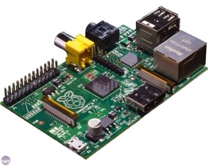
Such a marvelous little computer…

20131015-110724.jpg

Testing

Today I took a half day off and finished the greenhouse automation system enough to start testing it. Here it is ready to go.

20131011-220238.jpg

20131011-220253.jpg

Once I got it putting the data in the database I had to put together some web pages so I could keep track of what was going on. Come to find out one of my light sensors is messed up, so I’m going to make another. Back to the web tracking, you can see now there’s a link on the blog called “Greenhouse Conditions”. This shows all the data being collected now during the testing and it will be where I can check on it when it’s actually out there during the winter.

More sensors and etc…

Today I worked on completing the rest of my moisture sensors and then worked on some other sensors and things. This included the outside temp sensor, the main light sensor (as opposed to the individual ones for each tree) and connection of the powerswitch tail.

20131006-212921.jpg

The light sensor is on the right and the temp sensor is the metal rod on top. (You should be able to pick out the powerswitch tail from a precious post.) I decided to use an rj11 jack (phone jack) vs a rj45 (Ethernet jack) as at most I had 3 wires to deal with. I’ll review how I made the light sensor as it is the most difficult of the three.

20131006-212940.jpg

To make this you’ll need a LDR, a 10k ohm resistor, some phone cable, a rj11 jack (rj12 will work too), and some shrink tubes.

20131006-212949.jpg

For the tools you’ll need…a soldering iron and solder, some crimpers and strippers, a lighter, some scissors, a vice and a volt meter for testing.

20131006-213002.jpg

To start, strip off the protective sheathing and strip the black, red, and green wires. Connect the red wire to one side of the LDR, the green and the 10k ohm resistor to the other, and the black wire to the other side of the resistor. Be sure to place some shrink tube on the red wire prior to attaching the LDR to the wire.

20131006-213011.jpg

Next solder all the connections and place the shrink tube over the connection for the red wire and over the black wire and end of the resistor.

20131006-213023.jpg

Next place a larger piece of shrink tube over the whole wire and shrink it on to make sure the connections are undisturbed.

20131006-213034.jpg

After that side is completed, we need to add the jack to the other side. Strip back some of the sheathing on the cable and place your wires in this order (actually order doesn’t matter, but this is the order I use. )

20131006-213042.jpg

Make sure that your wires are all the same length and place them in the jack. Use your crimper to attach the jack to the wire. Now we should test our sensor.

20131006-213050.jpg

I forgot to include alligator clips in my tools pic, but they are very helpful for this step. To test I used a keystone jack connector and attached the wires shown to the correct place on the jack. I know this makes little sense, but green is red, white green is black, and orange is green. Connect the alligator clips to the wires and voltmeter. Set the voltmeter to 1M ohms resistance.

20131006-213058.jpg

20131006-213105.jpg

The images above show what you should be seeing when exposing your sensor to light or dark. As seen in the first image, you should get a fairly low reading when the sensor is exposed to light. When it is dark, the resistance goes very high and it will show the 0 as the voltmeter cannot read that high. (I think the LDRs I have are 10m ohms in the dark).

This sensor is going to give me a good idea of the overall light my trees receive and will be attached to the upside down basket that I use to protect the temp and humidity sensors from the sun. This sensor, like the individual tree LDRs that are in the moisture sensors gets plugged into a ADC. (Red wire is +3 volts, black is ground, and green is data and goes to ADC) Its pretty easy to use this sensor and when I get to my coding post I’ll show you the code required.

Tomorrow is softball and I won’t have any time to work on my project so I might post about growing wheat….

A Little Bit of Future Plans

Since I still have some work to go to have my sensors and everything working fully, I thought I’d talk a little about some of my later plans, particularly automatic watering.

As I’ve said previously, my current greenhouse automation will turn the heater on when it gets too cold, but that’s it. Now that’s very useful and saves a lot of electricity over me having to go out there and turn it on and off when it needs to be done. To accomplish this, I have a power switch tail hooked up to my system that basically is a switch that switches 110 volts with only 3v. This is a pretty simple device to use, you plug one end into a socket (I use an extension cord), then plug the device into the other end. Next, you plug some wires from your micro controller (or in my case your micro computer) into the power and ground in the power switch tail.

20131003-211453.jpg

Since I am able to control 110v devices with this device I can control a pump to move water from one place to another. So, my plan is to place a electric pump in a rain barrel and turn it on when the moisture level in the planters indicates that the soil is dry. I’ll hook the pump up to a drip system that will drip on all the trees.

20131003-202505.jpg

20131003-202511.jpg

This is the rain barrel and pump I plan on getting to accomplish this. I should be able to get both for maybe a little over $100. The one thing I kind of worry about is that the rain barrel only holds around 50 gallons and the pump will pump around 20 gallons per minute. I have to find out if there is a way I can tone it down a bit.

20131003-213157.jpg

The other thing I have thought about is not wanting the pump to run when there is no water in the barrel. To do this I can use this float switch. When the water is below a certain level in the barrel I will set the code to not turn the pump on. I’ll have to drill a hole in the barrel to install it, but it should be easy to attach it to the ADC to determine if the switch is open or closed. I plan on running the program every 5 minutes to do all the logging and checking of the sensors.

Moisture Sensor Circuit

Tonight I thought I would post on how the rest of the moisture sensor circuit works since I think I have it going correctly now. I was using a transistor that was switched by a digital pin when it was time to run the program, but when I put it all together to test, it didn’t work at all. So this is what I have at the moment; which seems to work with the two sensors I have built right now. More testing will be required after everything is completed.

20131003-013251.jpg

The first thing you’ll need is the rj45 female jack to plug your sensor into. Remember your order from previously as you’ll need to know which pins do what in your sensor.

When I created my sensors I used brown for into the moisture sensor, brown and white as out of the moisture sensor. Green was plus volts for the LDR and green and white is the ground side. The blue wire is the data wire; which leads us to the next step.

20131003-013302.jpg

From looking at my plug and memory, I know that pin 3 should be data for the LDR. I run a wire from pin 3 to my analog input. (I use a raspberry pi so I have to have an ADC (analog to digital converter) to convert the analog signals from the sensor to something the pi can understand.

20131003-013312.jpg

The next pin is pin 5 which is the brown wire or plus volts to the sensor. I connect this to a digital pin on my pi and in my code only set it to high (or power) when I need to so I don’t experience as much electrolysis. (I’ll show this in the code later.)

20131003-013321.jpg

Next is pin 6 which is brown and white or the other side of the sensor. This also needs to be connected to an analog input

This should tell you how much moisture is in the soil by the amount of volts that transverse the sensor.

20131003-013332.jpg

The next thing you’ll need to do is to put a pull down resistor on the yellow wire to ground. This is to pull the voltage reading down to zero when there is nothing going on with the sensor. I use a 10k ohm resistor for this

20131003-013341.jpg

20131003-013349.jpg

The last step is to connect pins 7 and 8 appropriately. Pin 7 is the green wire or power for the LDR (goes to +volts and pin 8 is the green and white wire ( aka ground for the LDR)

I still have a good amount of work to complete the automation system, but it seems to be coming along quite nicely.

Tomorrow I may show the code to
see how the relative moisture is captured or I may go to a different sensor (humidity, temperature, etc…)

Moisture Sensor

I recently decided that I needed to up my game when it came to my greenhouse automation, not because I’m lazy, but because I’m forgetful. My current system tracks the inside temp, outside temp and outside humidity and turns on a heater when it gets too cold. To accomplish this I use a raspberry pi with a ds18b20 temp sensor and a powerswitch tail 2.

Now I have since built some new planters for my citrus trees (will do a post on them later) and decided I needed to build a system that tells me when they need to be watered (and waters them, but that will come later as well). The first thing I needed to come up with was a moisture sensor to stick in the ground. This sensor measures both the relative moisture in the soil and the light the plant is receiving. This is what I eventually came up with:

20131001-201100.jpg

If you’re interested in making one if these you’ll need some parts:

20131001-201307.jpg

We need a 3″ piece of 1×2 cedar, a 3″ piece of 2″ craft board, some cat 5 cable, a rj45 jack, 10″ of 2×12 gauge electric wire, a LDR, a 10K ohm resistor, and some shrink tubing.

You’ll also need some tools and supplies:

20131001-201829.jpg

These include a soldering iron and solder, a rj45 crimper and some wire strippers, hot glue gun and glue sticks, a staple gun, pliers and a lighter.

20131001-202211.jpg

20131001-202220.jpg

The first step is to place the jack on one end of the cat 5 cable. To do this strip back some of the wrapper and separate the wires. Place them in the order you would like (I used this order as I like the colors next to their white counterparts). Place the wires in the jack and put in the crimper and press it on. Cat 5 cables allow you to have 8 wires, but we only use 5.

20131001-202229.jpg

The next step involves wiring up the LDR (light dependent resistor or light sensor). Strip of the wrapping on the other end (you’ll need a good amount) and separate the wires. I use the brown wire for plus volts into the moisture sensor, the brown and white wire for minus volts, the green wire for plus volts for the LDR, green and white for ground for the LDR and the blue wire for data on the LDR.

To wire the LDR you need to connect the green wire to one side (put your shrink tube over the wire before you connect them) the blue wire and one side of the 10k ohm resistor are connected to the other side of the LDR. The green and white wire is connected to the other side of the 10k ohm resistor. Once these are all connected solder them together to create a good solid connection.

20131001-202239.jpg

Once they’re all soldered put some shrink tube over the ground side of the LDR connection.

Next, we need to put together our moisture sensor probes. Use your strippers again to pull the black and white wires out of the 2×12 gauge wire.

20131001-202252.jpg

Once separated you will need to strip some off of each end of the wires. Just a little on the wire connection side and more on the side that will go into the ground.

20131001-202302.jpg

After this solder the ends of the probes that will be in the dirt to prevent erosion.

20131001-202312.jpg

Next, we need to connect the wires to the probes. Strip off a good bit from the cat 5 cables to make sure you can wrap it around the probe. Then solder the wires to the probes. (It helps to use a small vice to hold everything still while your soldering.

20131001-202323.jpg

After we are all connected, we need to “mount” the probes to the wood blocks. I align them as shown in the picture, then staple the with 2 staples for each probe. I then go and use some pliers to push the staples in securely.

20131001-202334.jpg

Almost finished!! Now we need to secure the LDR to the wood block. To do this I hold it down and use hot glue to secure it. I try to place the LDR a little above the top of the block. I also try to put some around all the other wires to make sure they don’t touch.

20131001-202354.jpg

20131001-202402.jpg

Finally, put the other piece of wood on top of everything and hot glue it together (this uses a lot of hot glue). I try not to cover the LDR with the glue but put it all around it.

20131001-202411.jpg

For good measure I staple the cat 5 cable to the back of the block to move it back to the top of the sensor block.

This really does have most of the circuit for the LDR, but for the moisture sensor I use a transistor to cut the ground when I’m not using the sensor to cut down on electrolysis. In another post I’ll write about how I go about using this sensor.

If you have any questions just post in the comments. I have made 2 of these so far and still have 4 to go!!