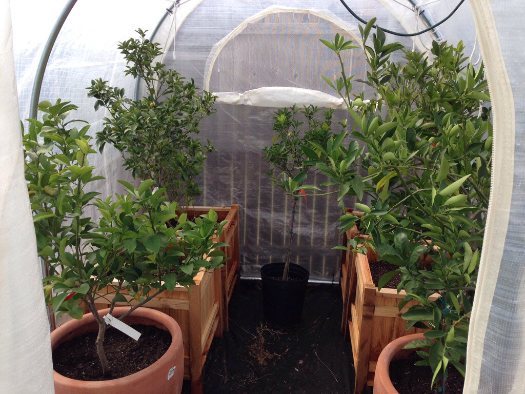
Today, I put the cover on the greenhouse to get ready for the winter. I know it’s a couple weeks early (as I don’t think we have the first frost here in Texas until around mid to late November. This year, I decided to use zip ties instead of rope to attach all the pieces and I think it worked a lot better. For those who haven’t seen it before here is my little greenhouse with all my citrus trees…
I’ve recently came to the understanding that I probably don’t need my automatic watering system nearly as much in the winter time, so I’m not in a rush anymore to get it built. When I will need it though is next summer. Now the fact that I need it most when I don’t have the cover on the greenhouse means that I need to find a way to waterproof everything. I’ve been looking into waterproof boxes I can put the computer in and have some ideas, but one of the other things I’ll need are waterproof moisture/light sensors for the trees. I had a revelation the other day that I can probably use some PVC to accomplish this. When I was at Lowes picking up the zip ties for the greenhouse, I went to the the plumbing section and found my parts.
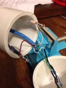
So, here it is, the new and improved waterproof (mostly. You can’t dip the whole thing in and expect it to survive. I haven’t really tested it’s waterproofness yet, but I believe it is)
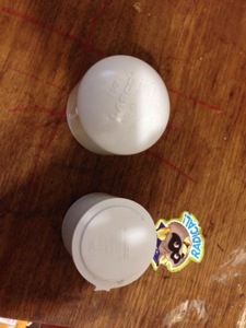
What you’ll need (besides many of the parts from the previous sensor) are a 1 1/2″ plug & a 1 1/2″ cap. (These should fit into each other.) The plug has a flat end and the cap has a rounded end. At first I had a hard time finding something that would work. I had planned on using some 1″ pipe with caps on either end, but I just didn’t think that the cap would be the right shape. When I was about to give up, I went back through one more time and found these!!! I was pretty excited that I found this combo.
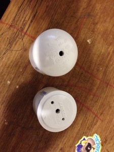
The first step to building this new sensor is to drill some holes in the cap and plug. You’ll need to drill a 7/32″ hole in the middle of both the cap and the plug. The plug also needs 2 1/8″ holes drilled on either side of the middle hole for the moisture sensor wire. The middle hole of the plug is for the cat 5 cable and the middle hole in the cap is for the light sensor.
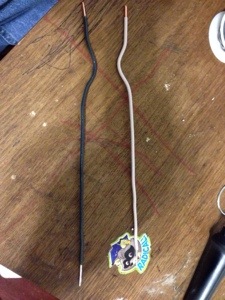
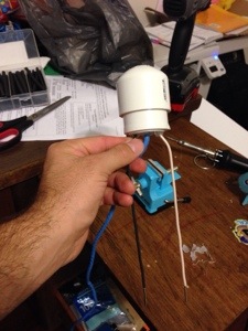
Again like the previous sensor, you’ll need to use some 12 gauge wire (10″ of romex is what I use). Remove some of the insulation from both sides like before and put some solder (tin) the side that will go into the dirt. When this is complete you’ll need to make your wires look like the above picture. The way to do this is the put the wire through it’s hole and then press the end against the side of the plug and hold it there. While holding the inside, bend the outside. You’ll want the part of the wire that has the insulation removed to be above the end of the plug. (I think this is shown later).
After you have the wires bent to the correct shape, you’ll need to “attach” the probes to the plug. Put them through the hole and then place some hot glue at around the probe where it meets the hole.

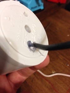
Next, flip the plug over and put a good amount of glue in the plug to hold the wire in place. (You can see in this picture how I said to place the part of the wire with the insulation removed above the top of the plug.) Do this with both sides one side at a time.
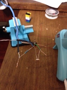
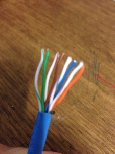
Now we go to the wiring part. Just like in the previous sensor, we’ll need a LDR and a 10 ohm resistor. Green to one side of the LDR, blue and one side of the 10 ohm resistor to the other side of the LDR, and green/white to the other side of the 10 ohm resistor. Solidify this connections with some solder and cover them with some shrink tube. (Make sure when you remove the insulation from the cat 5 cable that you have a good amount to work with.)
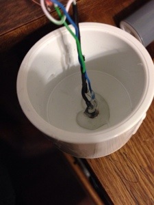
The next step is really annoying. You need to place the LDR in the hole in the cap and secure it. Do do this, I pushed the LDR through the hole and used some hot glue to tack it down. (Wait for it to dry so you have some hold.) Once it’s try, turn it over and place a lot of hot glue into the cap. Let this dry, then fill in the holes around the LDR on the other side of the cap. (It took me 5 tries to get this right.
Almost finished. Lets solder the brown wire to the black probe and the brown/white wire to the white probe. Should be pretty easy if you gave yourself enough wire and placed the top of the probe above the top of the plug. After you finished this you can carefully press the plug inside the cap. Once together, hot glue around where the cat 5 cable went enters the plug.
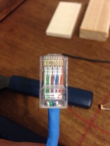
Finally, just as last time, place the rj45 jack on the end. I use the above pattern even though it doesn’t match the “standard” ethernet pattern. I’ve had this sensor going all day now and it seems to be working fine. I’d like to make another one to have two to test. I’ll need to do this fairly quickly as it’s getting close to when I need to take the system outside and actually work…