I finally completed migrating the weather sensors for the weather station that is at my father-in-law’s farm. I had issues with the rain gauge not working too well with the pi directly, so I decided to use an Adafruit Trinket to capture the values of the sensors and send them to the pi for tracking. The communication between the two is accomplished using I2C.
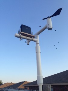
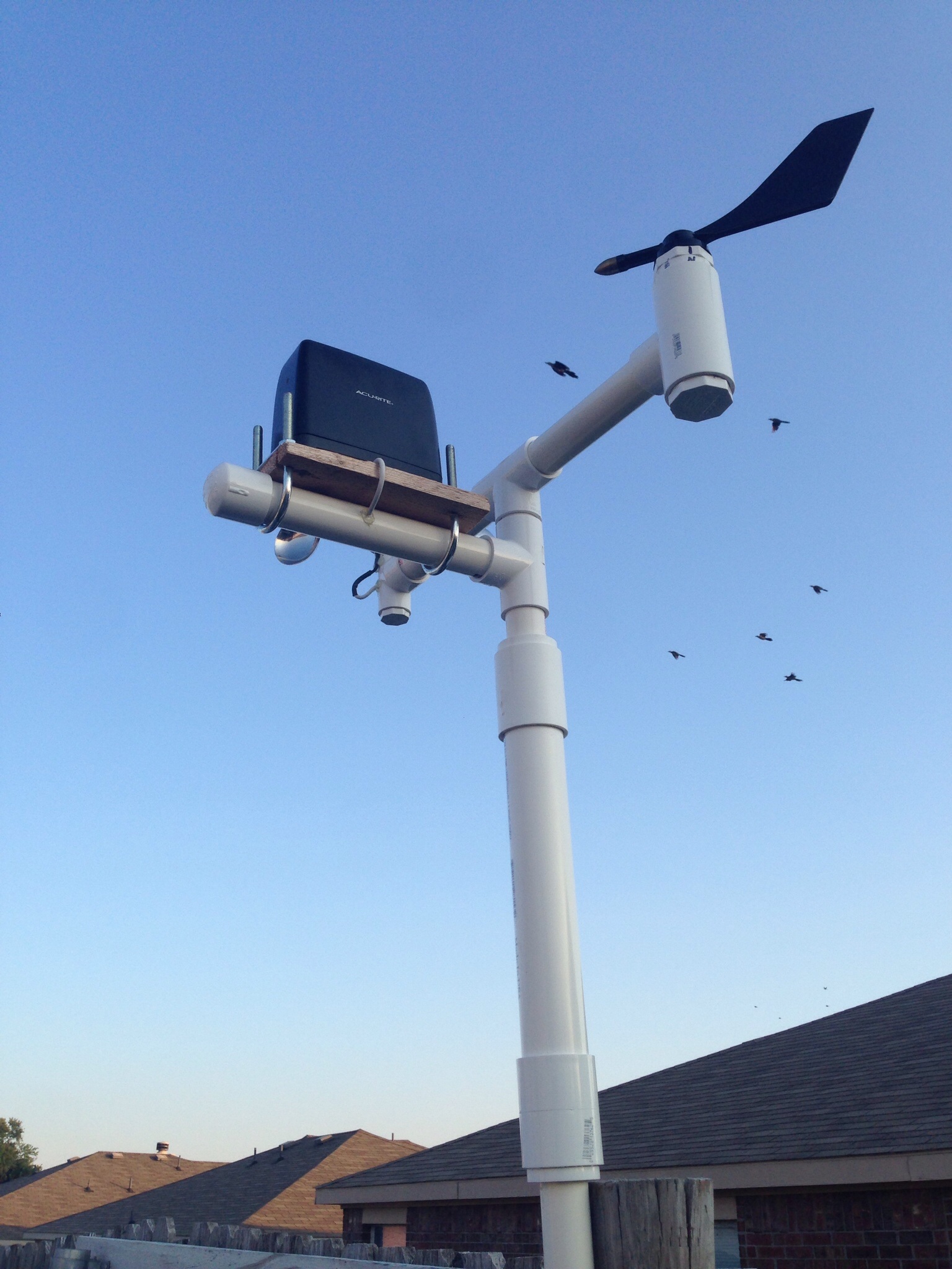
Here’s the completed mast with sensors attached. (This is actually a pic of it at my house for testing) What you’ll need for this is 1 of each of an anemometer, wind vane & rain gauge. It works with the sensors I built, but I’m sure you could incorporate it to use any sensors you have as well.
I’ve used PVC to build all my sensors as it’s easy to connect together. In my anemometer & wind vane posts I have used certain PVC pieces to allow for connection to my mast. For the rain gauge, it’s a little different. I used a piece of cedar fence board to secure the sensor, then some u-bolts to attach the board to a 1 inch pvc pipe, plugged one end and drilled a hole for the wire to run through.
For the rest of the top part of the mast I use a 1″ T-connector at the top with about 8 or so inches of 1″ pipe to connect the anemometer & wind vane. I run the wires down through the pipes. I then use a small piece of 1 inch pipe (about 3 or so inches) to connect another T-connector for the anemometer. I then use another portion of 3 or so inches of 1″ pvc pipe to connect to the lower portion. (Sorry, but I don’t have any pics of this…)
The lower mast is where the trinket comes in…I connect all the sensor wires to a single cat 5 cable to connect to trinket and then another wire for the I2C communication. The idea is to house the trinket in some 3/4″ pipe that is waterproofed and have it sit inside some 1 1/2″ pipe. (You can see this bulge in the pic above) I use some connectors to move from 1″ to 1 1/2″ pipe. Then a portion of 1 1/2″ pipe (I think it’s 12 inches long) and then connect it back to another 1″ piece of pipe to mount it.
Before wiring up your trinket, make sure you upload the code to it. Here is what I use which tracks the sensors and sends the data via I2C:
#include avr/interrupt.h
#include TinyWireS.h
// setup cbi & sbi for interrupts
#ifndef cbi
#define cbi(sfr, bit) (_SFR_BYTE(sfr) &= ~_BV(bit))
#endif
#ifndef sbi
#define sbi(sfr, bit) (_SFR_BYTE(sfr) |= _BV(bit))
#endif
//Define address of device
#define I2C_SLAVE_ADDRESS 0x04
// Set up registers to hold data to send
volatile uint8_t reg[] =
{
0xDE,
0xAD,
0xBE,
0xEF,
0xEE,
0xED
};
// Set up variables used
volatile byte reg_position; // keep track of reg position sent from master
volatile int rainGauge = 0; // keep track of interrupts from rain gauge
volatile int windSpeed = 0; // keep track of interrupts from anemometer
volatile int windDirection = 0; // keep track of value of wind direction sensor
volatile int windSpeedSend = 0; // used to send 10 second interrupt value to pi
long debouncing_time_rain = 300; //Debouncing Time in Milliseconds for rain gauge
volatile unsigned long last_micros_rain; // micros since last rain gauge interrput
long debouncing_time_wind = 100; //Debouncing Time in Milliseconds for anemometer
volatile unsigned long last_micros_wind; // micros since last anemometer interrupt
volatile int val1 = 0; // pin 1 value at interrupt
volatile int val2 = 0; // pin 4 value at interrupt
// Function to send data when it is requested. Sends 2 register positions
// for each request
void onRequest()
{
// Load all values into registers. (even though only 2 will go to master)
reg[0] = lowByte(windDirection);
reg[1] = highByte(windDirection);
reg[2] = lowByte(windSpeedSend);
reg[3] = highByte(windSpeedSend);
reg[4] = lowByte(rainGauge);
reg[5] = highByte(rainGauge);
// send 2 reg positions to master
TinyWireS.send(reg[reg_position]);
reg_position++;
}
// Function to set which register positions you wish to receive
void receiveEvent(uint8_t howMany)
{
reg_position = TinyWireS.receive();
// if requested position is 7, reset rain gauge variable. Will be sent at midnight each day
if(reg_position == 7) {
rainGauge = 0;
}
}
// Setup for connection
void setup()
{
TinyWireS.begin(I2C_SLAVE_ADDRESS);
TinyWireS.onReceive(receiveEvent);
TinyWireS.onRequest(onRequest);
pinMode(1,INPUT);
pinMode(4,INPUT);
sbi(GIMSK,PCIE); // Turn on Pin Change interrupt
sbi(PCMSK,PCINT1); // Which pins are affected by the interrupt. Turn on Pin 1
sbi(PCMSK,PCINT4); // Which pins are affected by the interrupt. Turn on Pin 2
}
void loop()
{
// anemometer counts interrupts for 10 second interval. This is sent to master for calculation
windSpeed = 0;
tws_delay(10000);
windSpeedSend = windSpeed;
// read pin 3 analog value of wind direction sensor
windDirection = analogRead(3);
// Check for connection to be stopped.
TinyWireS_stop_check();
}
// debounce rain gauge. make sure new reading is greater than old reading + debounce rain micros
void debounceRainGauge() {
if((long)(micros() – last_micros_rain) >= debouncing_time_rain * 1000) {
rainGaugeFunc();
last_micros_rain = micros();
}
}
// debounce anemometer. make sure new reading is greater than old reading + debounce wind micros
void debounceWindSpeed() {
if((long)(micros() – last_micros_wind) >= debouncing_time_wind * 1000) {
windSpeedFunc();
last_micros_wind = micros();
}
}
// function to increment rain gauge count
void rainGaugeFunc() {
rainGauge = rainGauge + 1;
} // end of rainGauge
// function to increment anemometer count
void windSpeedFunc() {
windSpeed = windSpeed + 1;
} // end of rainGauge
// interrupt service routine. What to do when an interrupt occurs as all pin change interrupts
// on ATTiny85 trigger PCINT0 vector.
ISR(PCINT0_vect) {
// get value of pin 1 @ interrupt
val1 = digitalRead(1);
// get value of pin 4 @ interrupt
val2 = digitalRead(4);
// if pin 1 is HIGH (caused the interrupt), proceed with rain gauge increment functions
if (val1 == HIGH) {
debounceRainGauge();
}
// if pin 4 is HIGH (caused the interrupt), proceed with wind speed (anemomether) increment function
if (val2 == HIGH) {
debounceWindSpeed();
}
}
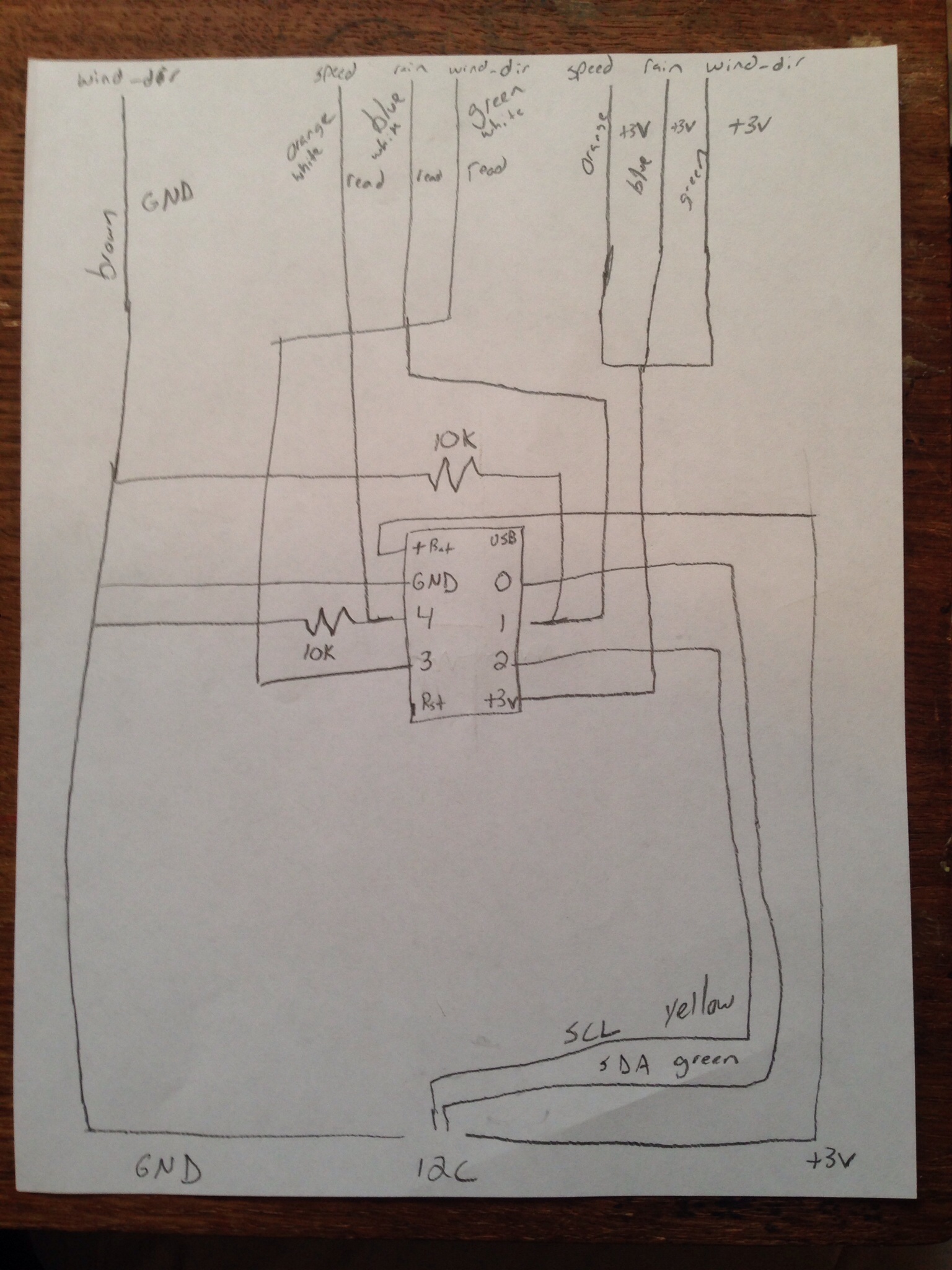
So, now to the wiring:
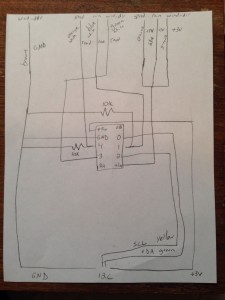
Here is the wiring diagram I drew out that shows how everything is connected. When connecting, make sure you use solder and shrink tube to protect the joints.
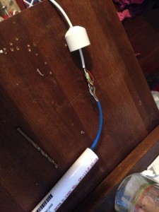
After all the wires are connected, drill a hole in a 3/4″ pvc plug and push the wire through that hole prior to connecting to the trinket. You may want to run it through a piece of 3/4″ pipe as well (about 8 or so inches).
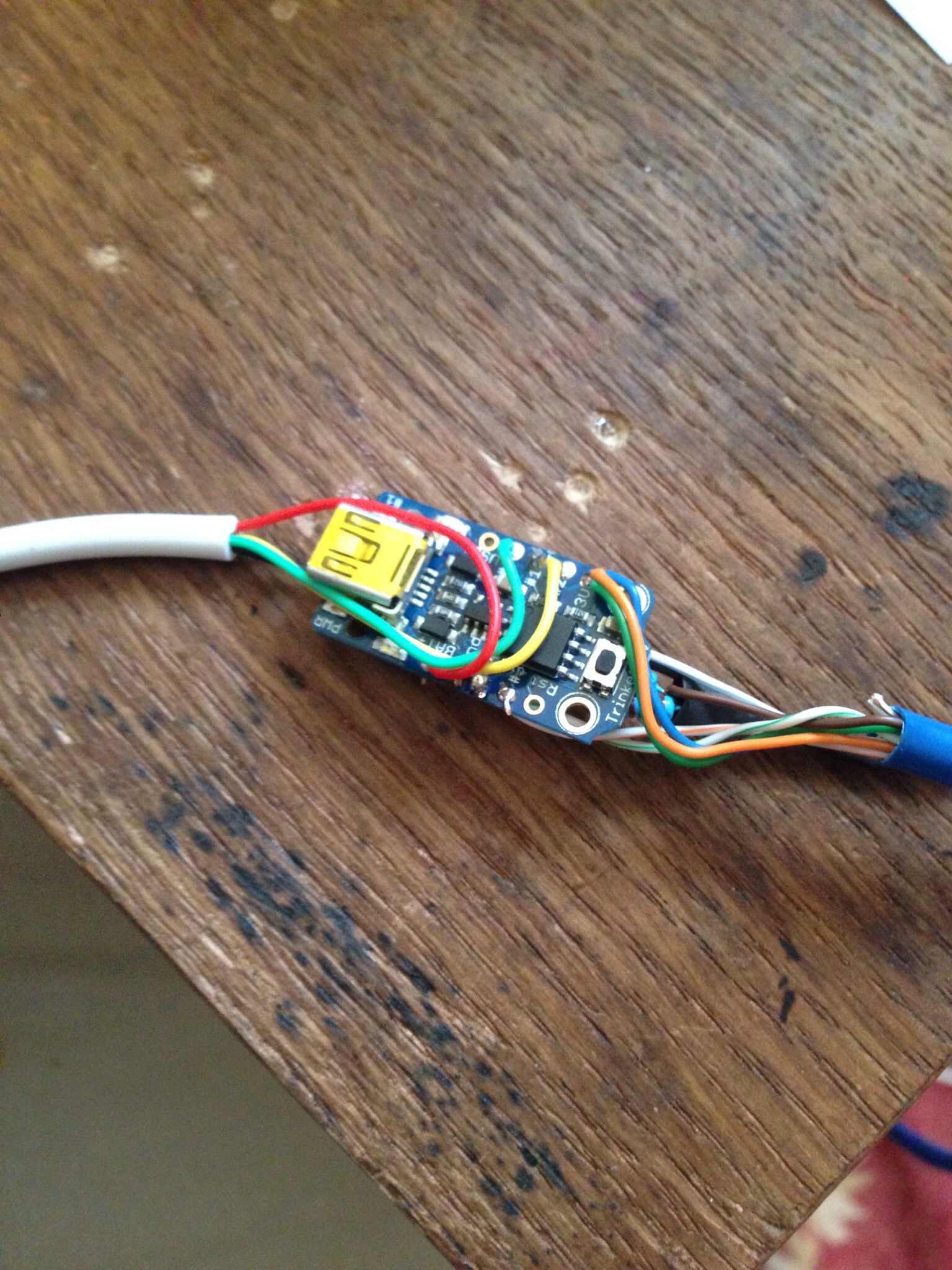
All 3 sensors will need 1 wire connected to the +3v on the sensor. I managed to get all 3 of the cat 5 wires into the hole on the trinket. The read wires will need to go different pins. For the anemometer and rain gauge, you will need to connect a 10k resistor to ground to pull the pin to ground. The rain gauge read wire should go to pin 1 and the read side of the anemometer should go to pin 4. The read wire for the wind vane should go to pin 3. Connecting all the ground wires was fun. What I did was run 1 wire out of the trinket and connected all the ground wires to it and put shrink tube over all of them. (You can see it in the pics below.)

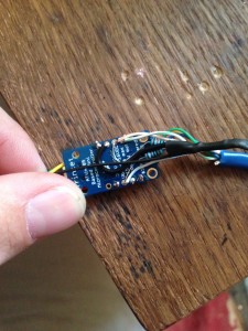
I didn’t take a lot of single step pics on this and I apologize. You can see the connections for the I2C wire as well in these pics. The last part is connecting the wires for the I2C communications. You’ll want to put the wire through hole in another 3/4″ pvc plug before you connect them to the trinket to allow for waterproofing. Connect the +v to the battery pin (I use 5 volts out of my raspberry pi to power, but you can power it any way you want. I used a 3 volt trinket for this setup). Ground to your ground wire, SDA to pin 0 and SCL to pin 2. Once this is done, slide it all into the 3/4″ pvc and plug the other side. It should look like this:
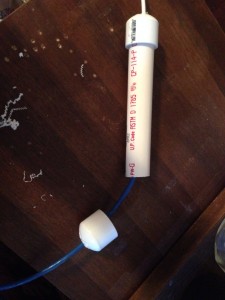
Place some hot glue on each plug where the wires go in to keep the water out, then shove this into the 1 1/2″ pvc pipe and then connect the rest of your mast.
This is really set up to communicate with a pi, but I’m pretty sure it would work with an Arduino as well. In the code you basically send the trinket a number and it will give you the response. Sending 0 will give you the wind direction reading, 2 will give you the wind speed reading and 4 will give you the rain gauge reading. Sending it 7 will cause the rain gauge count to reset. Here’s a quick bit of code you can use for the pi:
#!/usr/bin/python

# Import needed libraries

import smbus

import time
# Set I2C address of device you wish to access
DEV_ADDR = 0x04
bus = smbus.SMBus(1)
# Request values from device. Number is start register position.
while True:
print 'Testing for connection...'
while True:
try:
wind_dir_read = bus1.read_word_data(DEV_ADDR, 0)
wind_count = bus1.read_word_data(DEV_ADDR, 2)
rain_count = bus1.read_word_data(DEV_ADDR, 4)
break
except IOError:
print 'No connection...'
time.sleep(5)
#break
if wind_dir_read < 1030:
break
else:
print 'Value too high.'
time.sleep(5)
# Use this to reset a variable:
#d_val = bus.read_word_data(DEV_ADDR, 7)
It doesn't seem that wordpress knows how to deal with indents in it's code sections, so make sure you indent it properly. Sometimes the trinket can give you some funny business which I've handled via the error trapping above. If you keep this bit of code you shouldn't run into any problems.