Tonight I thought I would post on how the rest of the moisture sensor circuit works since I think I have it going correctly now. I was using a transistor that was switched by a digital pin when it was time to run the program, but when I put it all together to test, it didn’t work at all. So this is what I have at the moment; which seems to work with the two sensors I have built right now. More testing will be required after everything is completed.
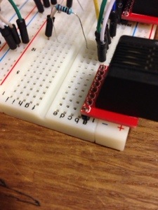
The first thing you’ll need is the rj45 female jack to plug your sensor into. Remember your order from previously as you’ll need to know which pins do what in your sensor.
When I created my sensors I used brown for into the moisture sensor, brown and white as out of the moisture sensor. Green was plus volts for the LDR and green and white is the ground side. The blue wire is the data wire; which leads us to the next step.
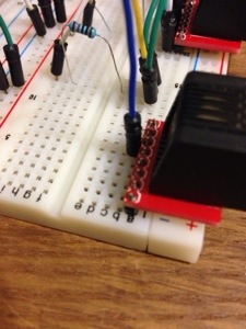
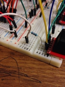
From looking at my plug and memory, I know that pin 3 should be data for the LDR. I run a wire from pin 3 to my analog input. (I use a raspberry pi so I have to have an ADC (analog to digital converter) to convert the analog signals from the sensor to something the pi can understand.
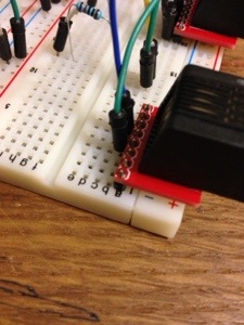
The next pin is pin 5 which is the brown wire or plus volts to the sensor. I connect this to a digital pin on my pi and in my code only set it to high (or power) when I need to so I don’t experience as much electrolysis. (I’ll show this in the code later.)
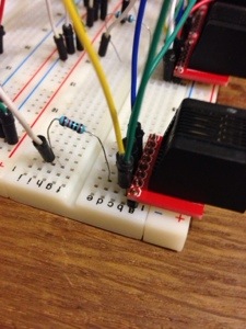
Next is pin 6 which is brown and white or the other side of the sensor. This also needs to be connected to an analog input
This should tell you how much moisture is in the soil by the amount of volts that transverse the sensor.
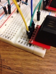
The next thing you’ll need to do is to put a pull down resistor on the yellow wire to ground. This is to pull the voltage reading down to zero when there is nothing going on with the sensor. I use a 10k ohm resistor for this
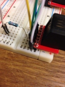
The last step is to connect pins 7 and 8 appropriately. Pin 7 is the green wire or power for the LDR (goes to +volts and pin 8 is the green and white wire ( aka ground for the LDR)
I still have a good amount of work to complete the automation system, but it seems to be coming along quite nicely.
Tomorrow I may show the code to
see how the relative moisture is captured or I may go to a different sensor (humidity, temperature, etc…)
No comments