Today I worked on completing the rest of my moisture sensors and then worked on some other sensors and things. This included the outside temp sensor, the main light sensor (as opposed to the individual ones for each tree) and connection of the powerswitch tail.
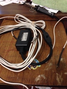
The light sensor is on the right and the temp sensor is the metal rod on top. (You should be able to pick out the powerswitch tail from a precious post.) I decided to use an rj11 jack (phone jack) vs a rj45 (Ethernet jack) as at most I had 3 wires to deal with. I’ll review how I made the light sensor as it is the most difficult of the three.
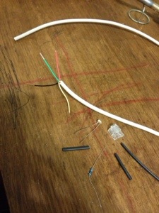
To make this you’ll need a LDR, a 10k ohm resistor, some phone cable, a rj11 jack (rj12 will work too), and some shrink tubes.
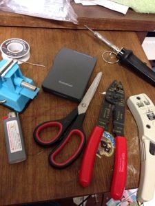
For the tools you’ll need…a soldering iron and solder, some crimpers and strippers, a lighter, some scissors, a vice and a volt meter for testing.
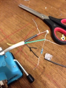
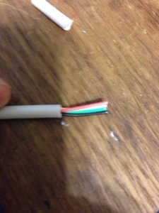
To start, strip off the protective sheathing and strip the black, red, and green wires. Connect the red wire to one side of the LDR, the green and the 10k ohm resistor to the other, and the black wire to the other side of the resistor. Be sure to place some shrink tube on the red wire prior to attaching the LDR to the wire.
Next solder all the connections and place the shrink tube over the connection for the red wire and over the black wire and end of the resistor.

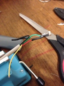
Next place a larger piece of shrink tube over the whole wire and shrink it on to make sure the connections are undisturbed.
After that side is completed, we need to add the jack to the other side. Strip back some of the sheathing on the cable and place your wires in this order (actually order doesn’t matter, but this is the order I use. )
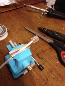
Make sure that your wires are all the same length and place them in the jack. Use your crimper to attach the jack to the wire. Now we should test our sensor.
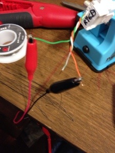
I forgot to include alligator clips in my tools pic, but they are very helpful for this step. To test I used a keystone jack connector and attached the wires shown to the correct place on the jack. I know this makes little sense, but green is red, white green is black, and orange is green. Connect the alligator clips to the wires and voltmeter. Set the voltmeter to 1M ohms resistance.
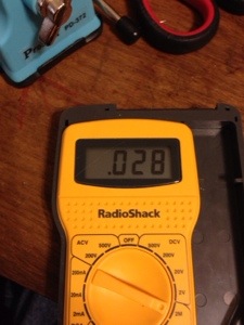
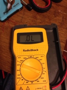
The images above show what you should be seeing when exposing your sensor to light or dark. As seen in the first image, you should get a fairly low reading when the sensor is exposed to light. When it is dark, the resistance goes very high and it will show the 0 as the voltmeter cannot read that high. (I think the LDRs I have are 10m ohms in the dark).
This sensor is going to give me a good idea of the overall light my trees receive and will be attached to the upside down basket that I use to protect the temp and humidity sensors from the sun. This sensor, like the individual tree LDRs that are in the moisture sensors gets plugged into a ADC. (Red wire is +3 volts, black is ground, and green is data and goes to ADC) Its pretty easy to use this sensor and when I get to my coding post I’ll show you the code required.
Tomorrow is softball and I won’t have any time to work on my project so I might post about growing wheat….
No comments