Archive for the ‘ Electronics ’ Category

Anemometer Reading

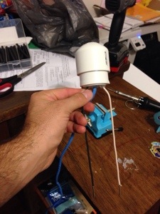
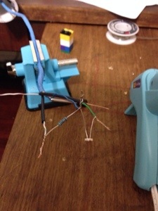
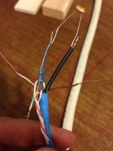
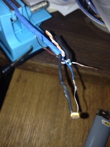
It was too late last night when I finished the post about building the anemometer that I didn’t want to get into the code to read the wind speed. As I said before, basically what I do is I count the number of “triggers” within a 10 second period and then feed that into the formula that came from testing it with our car.

Here is the code I use for Raspberry Pi…I run this every 5 minutes (with the rest of my measurements) to get the wind speed at that time.

# calculate windspeed
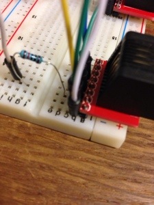
# set up the GPIO to be an input and activate the internal resistor to pull down the pin to low
GPIO.setup(22, GPIO.IN, pull_up_down=GPIO.PUD_DOWN)

# This is the interrupt function. It opens a file, pulls the number from the file and adds one to it, then rewrites it to the file.
def wind_callback(channel):
windfile = open("/home/pi/wind_count.txt")
windtext = windfile.readline()
windfile.close()

wind_count = int(windtext)
wind_count += 1
windfile = open("/home/pi/wind_count.txt", "w")

windfile.write(str(wind_count))
windfile.close()

# Here is the interrupt setup. We are setting it up on pin 22, looking for it to rise, calling the function "wind_callback" when it is triggered and
# debouncing it by 100ms
GPIO.add_event_detect(22, GPIO.RISING, callback=wind_callback, bouncetime=100)
# Before we start the count, we open the file and set the number to 0
windfile_clear = open("/home/pi/wind_count.txt", "w")
wind_count_clear = 0
windfile_clear.write(str(wind_count_clear))
windfile_clear.close()

# now we sleep for 10 seconds to get the readings
time.sleep(10)

# After sleeping, we open the file and read the number
wind_file = open("/home/pi/wind_count.txt")
wind_count = wind_file.readline()
wind_file.close()

# in order to use it in some math, we need to convert it to an int
wind_count_comp = int(wind_count)

# here is the formula created from testing. Basically it is .0023427x^2 + .46244x
windspeed_a = wind_count_comp * wind_count_comp * .0023427
windspeed_b = wind_count_comp * .46244
windspeed = windspeed_a + windspeed_b

# round it off to 1 decimal.
windspeed = round(windspeed, 1)

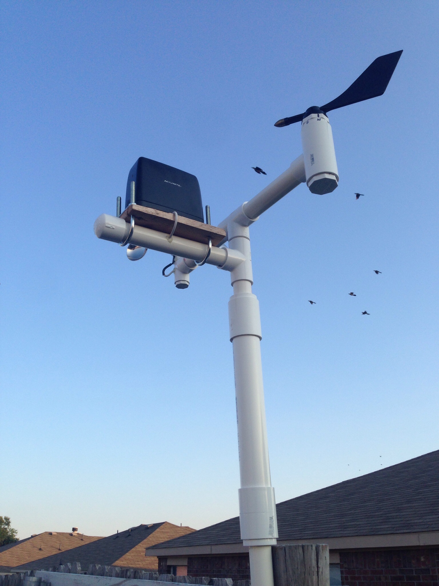
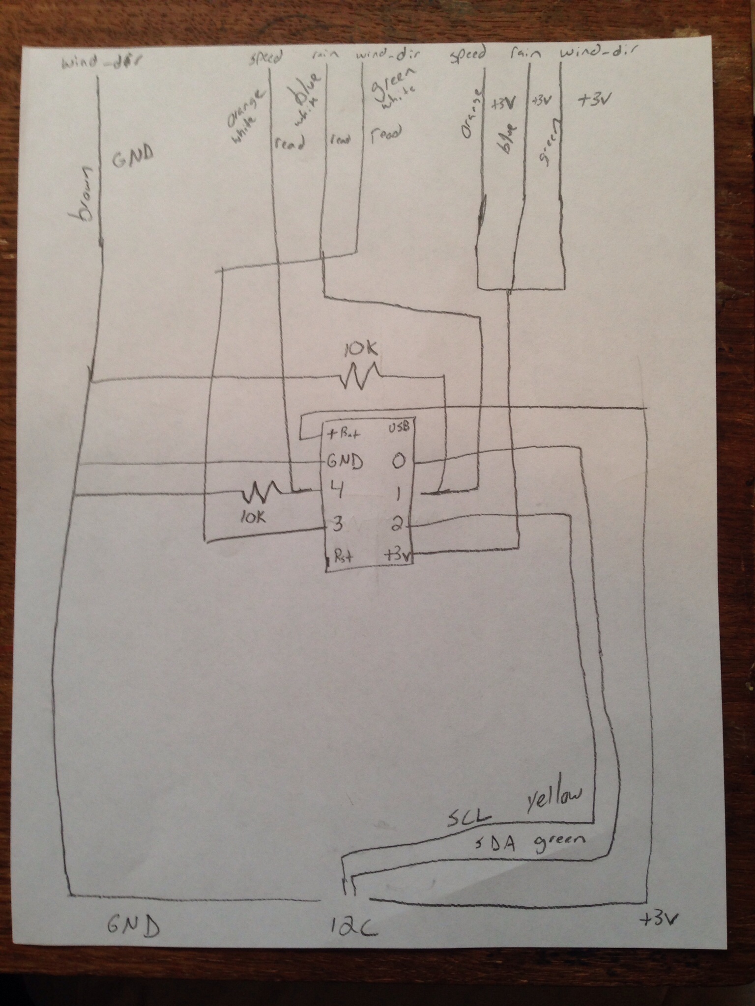
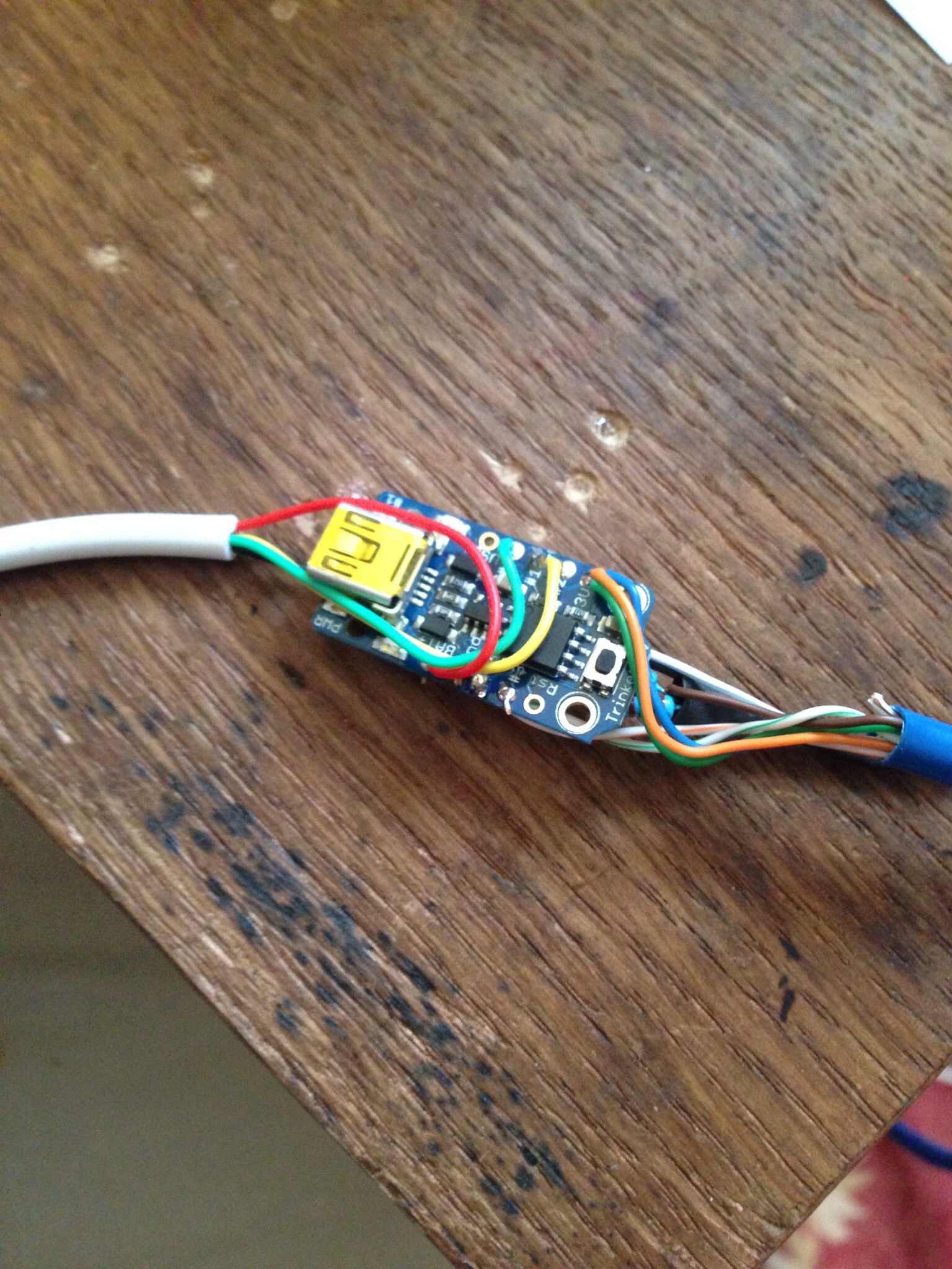
I am actually in the middle of a redesign on my weather station due to the Raspberry Pi not being the best at interrupts for the rain gauge. For the one at my father-in-laws farm, I will be using an Adafruit trinket to capture all the data from the anemometer, rain gauge, and wind direction sensor before relaying it to the Pi. This type of sensing is better for a micro controller than it is for a Linux computer such as the Pi. For my home weather station, I’ll be using a Arduino Pro Mini as I have a lot more sensors on my mast. The Trinket code is a little more difficult due to the ATTiny85 that runs it. I’ll post info on how to connect it to a Raspberry Pi later.

Here is the code for the same principal as above on a trinket. The big difference here is that this runs constantly. Every 10 seconds I have a wind speed reading, although I only pull it every 5 minutes.


#include avr/interrupt.h

// setup cbi & sbi for interrupts
#ifndef cbi
#define cbi(sfr, bit) (_SFR_BYTE(sfr) &= ~_BV(bit))
#endif
#ifndef sbi
#define sbi(sfr, bit) (_SFR_BYTE(sfr) |= _BV(bit))
#endif

// Set up variables used
volatile int windSpeed = 0; // keep track of interrupts from anemometer
volatile int windSpeedSend = 0; // used to send 10 second interrupt value to pi
long debouncing_time_wind = 100; //Debouncing Time in Milliseconds for anemometer
volatile unsigned long last_micros_wind; // micros since last anemometer interrupt
volatile int val2 = 0; // pin 4 value at interrupt

void setup()
{
// Setup Pins for interrupts
pinMode(4,INPUT);

sbi(GIMSK,PCIE); // Turn on Pin Change interrupt
sbi(PCMSK,PCINT4); // Which pins are affected by the interrupt. Turn on Pin 2

}

void loop()
{

// anemometer counts interrupts for 10 second interval. This is sent to master for calculation
windSpeed = 0;
tws_delay(10000);
windSpeedSend = windSpeed;

}

// debounce anemometer. make sure new reading is greater than old reading + debounce wind micros
void debounceWindSpeed() {
if((long)(micros() - last_micros_wind) >= debouncing_time_wind * 1000) {
windSpeedFunc();
last_micros_wind = micros();
}
}

// function to increment anemometer count
void windSpeedFunc() {
windSpeed = windSpeed + 1;
}

// interrupt service routine. What to do when an interrupt occurs as all pin change interrupts
// on ATTiny85 trigger PCINT0 vector.
ISR(PCINT0_vect) {
// get value of pin 4 @ interrupt
val2 = digitalRead(4);

// if pin 4 is HIGH (caused the interrupt), proceed with wind speed (anemomether) increment function
if (val2 == HIGH) {
debounceWindSpeed();
}

}

I finally completed migrating the weather sensors for the weather station that is at my father-in-law’s farm. I had issues with the rain gauge not working too well with the pi directly, so I decided to use an Adafruit Trinket to capture the values of the sensors and send them to the pi for tracking. The communication between the two is accomplished using I2C.

image

Here’s the completed mast with sensors attached. (This is actually a pic of it at my house for testing) What you’ll need for this is 1 of each of an anemometer, wind vane & rain gauge. It works with the sensors I built, but I’m sure you could incorporate it to use any sensors you have as well.

I’ve used PVC to build all my sensors as it’s easy to connect together. In my anemometer & wind vane posts I have used certain PVC pieces to allow for connection to my mast. For the rain gauge, it’s a little different. I used a piece of cedar fence board to secure the sensor, then some u-bolts to attach the board to a 1 inch pvc pipe, plugged one end and drilled a hole for the wire to run through.

For the rest of the top part of the mast I use a 1″ T-connector at the top with about 8 or so inches of 1″ pipe to connect the anemometer & wind vane. I run the wires down through the pipes. I then use a small piece of 1 inch pipe (about 3 or so inches) to connect another T-connector for the anemometer. I then use another portion of 3 or so inches of 1″ pvc pipe to connect to the lower portion. (Sorry, but I don’t have any pics of this…)

The lower mast is where the trinket comes in…I connect all the sensor wires to a single cat 5 cable to connect to trinket and then another wire for the I2C communication. The idea is to house the trinket in some 3/4″ pipe that is waterproofed and have it sit inside some 1 1/2″ pipe. (You can see this bulge in the pic above) I use some connectors to move from 1″ to 1 1/2″ pipe. Then a portion of 1 1/2″ pipe (I think it’s 12 inches long) and then connect it back to another 1″ piece of pipe to mount it.

Before wiring up your trinket, make sure you upload the code to it. Here is what I use which tracks the sensors and sends the data via I2C:

#include avr/interrupt.h
#include TinyWireS.h

// setup cbi & sbi for interrupts
#ifndef cbi
#define cbi(sfr, bit) (_SFR_BYTE(sfr) &= ~_BV(bit))
#endif
#ifndef sbi
#define sbi(sfr, bit) (_SFR_BYTE(sfr) |= _BV(bit))
#endif

//Define address of device
#define I2C_SLAVE_ADDRESS 0x04

// Set up registers to hold data to send
volatile uint8_t reg[] =
{

0xDE,
0xAD,
0xBE,
0xEF,
0xEE,
0xED
};

// Set up variables used

volatile byte reg_position; // keep track of reg position sent from master
volatile int rainGauge = 0; // keep track of interrupts from rain gauge
volatile int windSpeed = 0; // keep track of interrupts from anemometer
volatile int windDirection = 0; // keep track of value of wind direction sensor
volatile int windSpeedSend = 0; // used to send 10 second interrupt value to pi
long debouncing_time_rain = 300; //Debouncing Time in Milliseconds for rain gauge
volatile unsigned long last_micros_rain; // micros since last rain gauge interrput
long debouncing_time_wind = 100; //Debouncing Time in Milliseconds for anemometer
volatile unsigned long last_micros_wind; // micros since last anemometer interrupt
volatile int val1 = 0; // pin 1 value at interrupt
volatile int val2 = 0; // pin 4 value at interrupt

// Function to send data when it is requested. Sends 2 register positions
// for each request
void onRequest()
{

// Load all values into registers. (even though only 2 will go to master)
reg[0] = lowByte(windDirection);
reg[1] = highByte(windDirection);
reg[2] = lowByte(windSpeedSend);
reg[3] = highByte(windSpeedSend);
reg[4] = lowByte(rainGauge);
reg[5] = highByte(rainGauge);

// send 2 reg positions to master
TinyWireS.send(reg[reg_position]);
reg_position++;

}
// Function to set which register positions you wish to receive
void receiveEvent(uint8_t howMany)
{
reg_position = TinyWireS.receive();

// if requested position is 7, reset rain gauge variable. Will be sent at midnight each day
if(reg_position == 7) {
rainGauge = 0;
}

}

// Setup for connection
void setup()
{
TinyWireS.begin(I2C_SLAVE_ADDRESS);
TinyWireS.onReceive(receiveEvent);
TinyWireS.onRequest(onRequest);
pinMode(1,INPUT);
pinMode(4,INPUT);

sbi(GIMSK,PCIE); // Turn on Pin Change interrupt
sbi(PCMSK,PCINT1); // Which pins are affected by the interrupt. Turn on Pin 1
sbi(PCMSK,PCINT4); // Which pins are affected by the interrupt. Turn on Pin 2
}

void loop()
{

// anemometer counts interrupts for 10 second interval. This is sent to master for calculation
windSpeed = 0;
tws_delay(10000);
windSpeedSend = windSpeed;

// read pin 3 analog value of wind direction sensor
windDirection = analogRead(3);

// Check for connection to be stopped.
TinyWireS_stop_check();
}

// debounce rain gauge. make sure new reading is greater than old reading + debounce rain micros
void debounceRainGauge() {
if((long)(micros() – last_micros_rain) >= debouncing_time_rain * 1000) {
rainGaugeFunc();
last_micros_rain = micros();
}
}

// debounce anemometer. make sure new reading is greater than old reading + debounce wind micros
void debounceWindSpeed() {
if((long)(micros() – last_micros_wind) >= debouncing_time_wind * 1000) {
windSpeedFunc();
last_micros_wind = micros();
}
}

// function to increment rain gauge count
void rainGaugeFunc() {
rainGauge = rainGauge + 1;
} // end of rainGauge

// function to increment anemometer count
void windSpeedFunc() {
windSpeed = windSpeed + 1;
} // end of rainGauge

// interrupt service routine. What to do when an interrupt occurs as all pin change interrupts
// on ATTiny85 trigger PCINT0 vector.
ISR(PCINT0_vect) {
// get value of pin 1 @ interrupt
val1 = digitalRead(1);
// get value of pin 4 @ interrupt
val2 = digitalRead(4);

// if pin 1 is HIGH (caused the interrupt), proceed with rain gauge increment functions
if (val1 == HIGH) {
debounceRainGauge();
}

// if pin 4 is HIGH (caused the interrupt), proceed with wind speed (anemomether) increment function
if (val2 == HIGH) {
debounceWindSpeed();
}

}

So, now to the wiring:
image

Here is the wiring diagram I drew out that shows how everything is connected. When connecting, make sure you use solder and shrink tube to protect the joints.

image

After all the wires are connected, drill a hole in a 3/4″ pvc plug and push the wire through that hole prior to connecting to the trinket. You may want to run it through a piece of 3/4″ pipe as well (about 8 or so inches).

All 3 sensors will need 1 wire connected to the +3v on the sensor. I managed to get all 3 of the cat 5 wires into the hole on the trinket. The read wires will need to go different pins. For the anemometer and rain gauge, you will need to connect a 10k resistor to ground to pull the pin to ground. The rain gauge read wire should go to pin 1 and the read side of the anemometer should go to pin 4. The read wire for the wind vane should go to pin 3. Connecting all the ground wires was fun. What I did was run 1 wire out of the trinket and connected all the ground wires to it and put shrink tube over all of them. (You can see it in the pics below.)

image

image

I didn’t take a lot of single step pics on this and I apologize. You can see the connections for the I2C wire as well in these pics. The last part is connecting the wires for the I2C communications. You’ll want to put the wire through hole in another 3/4″ pvc plug before you connect them to the trinket to allow for waterproofing. Connect the +v to the battery pin (I use 5 volts out of my raspberry pi to power, but you can power it any way you want. I used a 3 volt trinket for this setup). Ground to your ground wire, SDA to pin 0 and SCL to pin 2. Once this is done, slide it all into the 3/4″ pvc and plug the other side. It should look like this:

image

Place some hot glue on each plug where the wires go in to keep the water out, then shove this into the 1 1/2″ pvc pipe and then connect the rest of your mast.

This is really set up to communicate with a pi, but I’m pretty sure it would work with an Arduino as well. In the code you basically send the trinket a number and it will give you the response. Sending 0 will give you the wind direction reading, 2 will give you the wind speed reading and 4 will give you the rain gauge reading. Sending it 7 will cause the rain gauge count to reset. Here’s a quick bit of code you can use for the pi:


#!/usr/bin/python
# Import needed libraries
import smbus
import time

# Set I2C address of device you wish to access
DEV_ADDR = 0x04

bus = smbus.SMBus(1)

# Request values from device. Number is start register position.
while True:
print 'Testing for connection...'
while True:
try:
wind_dir_read = bus1.read_word_data(DEV_ADDR, 0)
wind_count = bus1.read_word_data(DEV_ADDR, 2)
rain_count = bus1.read_word_data(DEV_ADDR, 4)
break
except IOError:
print 'No connection...'
time.sleep(5)
#break
if wind_dir_read < 1030: break else: print 'Value too high.' time.sleep(5) # Use this to reset a variable: #d_val = bus.read_word_data(DEV_ADDR, 7)

It doesn't seem that wordpress knows how to deal with indents in it's code sections, so make sure you indent it properly. Sometimes the trinket can give you some funny business which I've handled via the error trapping above. If you keep this bit of code you shouldn't run into any problems.

Weather Station

20131128-093102.jpg

I know it’s been a while since I posted something, I guess it was just getting difficult to find time to post something after completing a sensor before bed. My most recent project has been building my own weather station. This sort of came from the greenhouse automation project. Once I was able to measure humidity, that was it; I wanted to measure everything else about the weather that I could.

In building this, I feel I learned a lot about some other aspects of the raspberry pi, coding and some other sensors (reed switches specifically). In some places, I kind of took the easy route and took something someone else made and re-wired it to work for me, (rain gauge & wind direction pointer) but this still involved a lot of innovation on the coding side to use it. I plan to write other posts detailing the building of the other sensors; just plan to space them out some as some of them are pretty involved. I think eventually I might make a wireless self-contained version (wifi, batteries, & solar power), but that’ll be a while 😉

Oh…..forgot to mention the first time I published it…..you can see the current weather at my house by clicking on the “Current Weather” page on my blog…

Today, I put the cover on the greenhouse to get ready for the winter. I know it’s a couple weeks early (as I don’t think we have the first frost here in Texas until around mid to late November. This year, I decided to use zip ties instead of rope to attach all the pieces and I think it worked a lot better. For those who haven’t seen it before here is my little greenhouse with all my citrus trees…

20131026-212217.jpg

I’ve recently came to the understanding that I probably don’t need my automatic watering system nearly as much in the winter time, so I’m not in a rush anymore to get it built. When I will need it though is next summer. Now the fact that I need it most when I don’t have the cover on the greenhouse means that I need to find a way to waterproof everything. I’ve been looking into waterproof boxes I can put the computer in and have some ideas, but one of the other things I’ll need are waterproof moisture/light sensors for the trees. I had a revelation the other day that I can probably use some PVC to accomplish this. When I was at Lowes picking up the zip ties for the greenhouse, I went to the the plumbing section and found my parts.

20131026-212352.jpg

So, here it is, the new and improved waterproof (mostly. You can’t dip the whole thing in and expect it to survive. I haven’t really tested it’s waterproofness yet, but I believe it is)

20131026-212226.jpg

What you’ll need (besides many of the parts from the previous sensor) are a 1 1/2″ plug & a 1 1/2″ cap. (These should fit into each other.) The plug has a flat end and the cap has a rounded end. At first I had a hard time finding something that would work. I had planned on using some 1″ pipe with caps on either end, but I just didn’t think that the cap would be the right shape. When I was about to give up, I went back through one more time and found these!!! I was pretty excited that I found this combo.

20131026-212233.jpg

The first step to building this new sensor is to drill some holes in the cap and plug. You’ll need to drill a 7/32″ hole in the middle of both the cap and the plug. The plug also needs 2 1/8″ holes drilled on either side of the middle hole for the moisture sensor wire. The middle hole of the plug is for the cat 5 cable and the middle hole in the cap is for the light sensor.

20131026-212241.jpg

Again like the previous sensor, you’ll need to use some 12 gauge wire (10″ of romex is what I use). Remove some of the insulation from both sides like before and put some solder (tin) the side that will go into the dirt. When this is complete you’ll need to make your wires look like the above picture. The way to do this is the put the wire through it’s hole and then press the end against the side of the plug and hold it there. While holding the inside, bend the outside. You’ll want the part of the wire that has the insulation removed to be above the end of the plug. (I think this is shown later).

20131026-212248.jpg

After you have the wires bent to the correct shape, you’ll need to “attach” the probes to the plug. Put them through the hole and then place some hot glue at around the probe where it meets the hole.

20131026-212255.jpg

Next, flip the plug over and put a good amount of glue in the plug to hold the wire in place. (You can see in this picture how I said to place the part of the wire with the insulation removed above the top of the plug.) Do this with both sides one side at a time.

20131026-212314.jpg

Now we go to the wiring part. Just like in the previous sensor, we’ll need a LDR and a 10 ohm resistor. Green to one side of the LDR, blue and one side of the 10 ohm resistor to the other side of the LDR, and green/white to the other side of the 10 ohm resistor. Solidify this connections with some solder and cover them with some shrink tube. (Make sure when you remove the insulation from the cat 5 cable that you have a good amount to work with.)

20131026-212321.jpg

The next step is really annoying. You need to place the LDR in the hole in the cap and secure it. Do do this, I pushed the LDR through the hole and used some hot glue to tack it down. (Wait for it to dry so you have some hold.) Once it’s try, turn it over and place a lot of hot glue into the cap. Let this dry, then fill in the holes around the LDR on the other side of the cap. (It took me 5 tries to get this right.

20131026-212332.jpg

Almost finished. Lets solder the brown wire to the black probe and the brown/white wire to the white probe. Should be pretty easy if you gave yourself enough wire and placed the top of the probe above the top of the plug. After you finished this you can carefully press the plug inside the cap. Once together, hot glue around where the cat 5 cable went enters the plug.

20131026-212359.jpg

20131026-212404.jpg

Finally, just as last time, place the rj45 jack on the end. I use the above pattern even though it doesn’t match the “standard” ethernet pattern. I’ve had this sensor going all day now and it seems to be working fine. I’d like to make another one to have two to test. I’ll need to do this fairly quickly as it’s getting close to when I need to take the system outside and actually work…

Testing

Today I took a half day off and finished the greenhouse automation system enough to start testing it. Here it is ready to go.

20131011-220238.jpg

20131011-220253.jpg

Once I got it putting the data in the database I had to put together some web pages so I could keep track of what was going on. Come to find out one of my light sensors is messed up, so I’m going to make another. Back to the web tracking, you can see now there’s a link on the blog called “Greenhouse Conditions”. This shows all the data being collected now during the testing and it will be where I can check on it when it’s actually out there during the winter.

More sensors and etc…

Today I worked on completing the rest of my moisture sensors and then worked on some other sensors and things. This included the outside temp sensor, the main light sensor (as opposed to the individual ones for each tree) and connection of the powerswitch tail.

20131006-212921.jpg

The light sensor is on the right and the temp sensor is the metal rod on top. (You should be able to pick out the powerswitch tail from a precious post.) I decided to use an rj11 jack (phone jack) vs a rj45 (Ethernet jack) as at most I had 3 wires to deal with. I’ll review how I made the light sensor as it is the most difficult of the three.

20131006-212940.jpg

To make this you’ll need a LDR, a 10k ohm resistor, some phone cable, a rj11 jack (rj12 will work too), and some shrink tubes.

20131006-212949.jpg

For the tools you’ll need…a soldering iron and solder, some crimpers and strippers, a lighter, some scissors, a vice and a volt meter for testing.

20131006-213002.jpg

To start, strip off the protective sheathing and strip the black, red, and green wires. Connect the red wire to one side of the LDR, the green and the 10k ohm resistor to the other, and the black wire to the other side of the resistor. Be sure to place some shrink tube on the red wire prior to attaching the LDR to the wire.

20131006-213011.jpg

Next solder all the connections and place the shrink tube over the connection for the red wire and over the black wire and end of the resistor.

20131006-213023.jpg

Next place a larger piece of shrink tube over the whole wire and shrink it on to make sure the connections are undisturbed.

20131006-213034.jpg

After that side is completed, we need to add the jack to the other side. Strip back some of the sheathing on the cable and place your wires in this order (actually order doesn’t matter, but this is the order I use. )

20131006-213042.jpg

Make sure that your wires are all the same length and place them in the jack. Use your crimper to attach the jack to the wire. Now we should test our sensor.

20131006-213050.jpg

I forgot to include alligator clips in my tools pic, but they are very helpful for this step. To test I used a keystone jack connector and attached the wires shown to the correct place on the jack. I know this makes little sense, but green is red, white green is black, and orange is green. Connect the alligator clips to the wires and voltmeter. Set the voltmeter to 1M ohms resistance.

20131006-213058.jpg

20131006-213105.jpg

The images above show what you should be seeing when exposing your sensor to light or dark. As seen in the first image, you should get a fairly low reading when the sensor is exposed to light. When it is dark, the resistance goes very high and it will show the 0 as the voltmeter cannot read that high. (I think the LDRs I have are 10m ohms in the dark).

This sensor is going to give me a good idea of the overall light my trees receive and will be attached to the upside down basket that I use to protect the temp and humidity sensors from the sun. This sensor, like the individual tree LDRs that are in the moisture sensors gets plugged into a ADC. (Red wire is +3 volts, black is ground, and green is data and goes to ADC) Its pretty easy to use this sensor and when I get to my coding post I’ll show you the code required.

Tomorrow is softball and I won’t have any time to work on my project so I might post about growing wheat….

A Little Bit of Future Plans

Since I still have some work to go to have my sensors and everything working fully, I thought I’d talk a little about some of my later plans, particularly automatic watering.

As I’ve said previously, my current greenhouse automation will turn the heater on when it gets too cold, but that’s it. Now that’s very useful and saves a lot of electricity over me having to go out there and turn it on and off when it needs to be done. To accomplish this, I have a power switch tail hooked up to my system that basically is a switch that switches 110 volts with only 3v. This is a pretty simple device to use, you plug one end into a socket (I use an extension cord), then plug the device into the other end. Next, you plug some wires from your micro controller (or in my case your micro computer) into the power and ground in the power switch tail.

20131003-211453.jpg

Since I am able to control 110v devices with this device I can control a pump to move water from one place to another. So, my plan is to place a electric pump in a rain barrel and turn it on when the moisture level in the planters indicates that the soil is dry. I’ll hook the pump up to a drip system that will drip on all the trees.

20131003-202505.jpg

20131003-202511.jpg

This is the rain barrel and pump I plan on getting to accomplish this. I should be able to get both for maybe a little over $100. The one thing I kind of worry about is that the rain barrel only holds around 50 gallons and the pump will pump around 20 gallons per minute. I have to find out if there is a way I can tone it down a bit.

20131003-213157.jpg

The other thing I have thought about is not wanting the pump to run when there is no water in the barrel. To do this I can use this float switch. When the water is below a certain level in the barrel I will set the code to not turn the pump on. I’ll have to drill a hole in the barrel to install it, but it should be easy to attach it to the ADC to determine if the switch is open or closed. I plan on running the program every 5 minutes to do all the logging and checking of the sensors.

Moisture Sensor Circuit

Tonight I thought I would post on how the rest of the moisture sensor circuit works since I think I have it going correctly now. I was using a transistor that was switched by a digital pin when it was time to run the program, but when I put it all together to test, it didn’t work at all. So this is what I have at the moment; which seems to work with the two sensors I have built right now. More testing will be required after everything is completed.

20131003-013251.jpg

The first thing you’ll need is the rj45 female jack to plug your sensor into. Remember your order from previously as you’ll need to know which pins do what in your sensor.

When I created my sensors I used brown for into the moisture sensor, brown and white as out of the moisture sensor. Green was plus volts for the LDR and green and white is the ground side. The blue wire is the data wire; which leads us to the next step.

20131003-013302.jpg

From looking at my plug and memory, I know that pin 3 should be data for the LDR. I run a wire from pin 3 to my analog input. (I use a raspberry pi so I have to have an ADC (analog to digital converter) to convert the analog signals from the sensor to something the pi can understand.

20131003-013312.jpg

The next pin is pin 5 which is the brown wire or plus volts to the sensor. I connect this to a digital pin on my pi and in my code only set it to high (or power) when I need to so I don’t experience as much electrolysis. (I’ll show this in the code later.)

20131003-013321.jpg

Next is pin 6 which is brown and white or the other side of the sensor. This also needs to be connected to an analog input

This should tell you how much moisture is in the soil by the amount of volts that transverse the sensor.

20131003-013332.jpg

The next thing you’ll need to do is to put a pull down resistor on the yellow wire to ground. This is to pull the voltage reading down to zero when there is nothing going on with the sensor. I use a 10k ohm resistor for this

20131003-013341.jpg

20131003-013349.jpg

The last step is to connect pins 7 and 8 appropriately. Pin 7 is the green wire or power for the LDR (goes to +volts and pin 8 is the green and white wire ( aka ground for the LDR)

I still have a good amount of work to complete the automation system, but it seems to be coming along quite nicely.

Tomorrow I may show the code to
see how the relative moisture is captured or I may go to a different sensor (humidity, temperature, etc…)

Moisture Sensor

I recently decided that I needed to up my game when it came to my greenhouse automation, not because I’m lazy, but because I’m forgetful. My current system tracks the inside temp, outside temp and outside humidity and turns on a heater when it gets too cold. To accomplish this I use a raspberry pi with a ds18b20 temp sensor and a powerswitch tail 2.

Now I have since built some new planters for my citrus trees (will do a post on them later) and decided I needed to build a system that tells me when they need to be watered (and waters them, but that will come later as well). The first thing I needed to come up with was a moisture sensor to stick in the ground. This sensor measures both the relative moisture in the soil and the light the plant is receiving. This is what I eventually came up with:

20131001-201100.jpg

If you’re interested in making one if these you’ll need some parts:

20131001-201307.jpg

We need a 3″ piece of 1×2 cedar, a 3″ piece of 2″ craft board, some cat 5 cable, a rj45 jack, 10″ of 2×12 gauge electric wire, a LDR, a 10K ohm resistor, and some shrink tubing.

You’ll also need some tools and supplies:

20131001-201829.jpg

These include a soldering iron and solder, a rj45 crimper and some wire strippers, hot glue gun and glue sticks, a staple gun, pliers and a lighter.

20131001-202211.jpg

20131001-202220.jpg

The first step is to place the jack on one end of the cat 5 cable. To do this strip back some of the wrapper and separate the wires. Place them in the order you would like (I used this order as I like the colors next to their white counterparts). Place the wires in the jack and put in the crimper and press it on. Cat 5 cables allow you to have 8 wires, but we only use 5.

20131001-202229.jpg

The next step involves wiring up the LDR (light dependent resistor or light sensor). Strip of the wrapping on the other end (you’ll need a good amount) and separate the wires. I use the brown wire for plus volts into the moisture sensor, the brown and white wire for minus volts, the green wire for plus volts for the LDR, green and white for ground for the LDR and the blue wire for data on the LDR.

To wire the LDR you need to connect the green wire to one side (put your shrink tube over the wire before you connect them) the blue wire and one side of the 10k ohm resistor are connected to the other side of the LDR. The green and white wire is connected to the other side of the 10k ohm resistor. Once these are all connected solder them together to create a good solid connection.

20131001-202239.jpg

Once they’re all soldered put some shrink tube over the ground side of the LDR connection.

Next, we need to put together our moisture sensor probes. Use your strippers again to pull the black and white wires out of the 2×12 gauge wire.

20131001-202252.jpg

Once separated you will need to strip some off of each end of the wires. Just a little on the wire connection side and more on the side that will go into the ground.

20131001-202302.jpg

After this solder the ends of the probes that will be in the dirt to prevent erosion.

20131001-202312.jpg

Next, we need to connect the wires to the probes. Strip off a good bit from the cat 5 cables to make sure you can wrap it around the probe. Then solder the wires to the probes. (It helps to use a small vice to hold everything still while your soldering.

20131001-202323.jpg

After we are all connected, we need to “mount” the probes to the wood blocks. I align them as shown in the picture, then staple the with 2 staples for each probe. I then go and use some pliers to push the staples in securely.

20131001-202334.jpg

Almost finished!! Now we need to secure the LDR to the wood block. To do this I hold it down and use hot glue to secure it. I try to place the LDR a little above the top of the block. I also try to put some around all the other wires to make sure they don’t touch.

20131001-202354.jpg

20131001-202402.jpg

Finally, put the other piece of wood on top of everything and hot glue it together (this uses a lot of hot glue). I try not to cover the LDR with the glue but put it all around it.

20131001-202411.jpg

For good measure I staple the cat 5 cable to the back of the block to move it back to the top of the sensor block.

This really does have most of the circuit for the LDR, but for the moisture sensor I use a transistor to cut the ground when I’m not using the sensor to cut down on electrolysis. In another post I’ll write about how I go about using this sensor.

If you have any questions just post in the comments. I have made 2 of these so far and still have 4 to go!!